


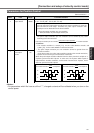
147
[Connection and setup of velocity control mode]
Connection and Setup of
Velocity Control Mode
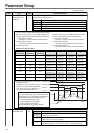
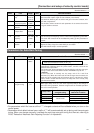
19
1A
1B
1C
1 to 3500
A to C-frame:<35>*
D to F-frame:<18>*
1 to 1000
<1000>*
0 to 5
<0>*
0 to 2500
A to C-frame:<65>*
D to F-frame:<126>*
Hz
ms
–
0.01ms
2nd gain of velocity
loop
2nd time constant of
velocity loop integration
2nd filter of velocity
detection
2nd time constant
of torque filter
Position loop, velocity loop, speed detection filter and torque command
filter have their 2 pairs of gain or time constant (1st and 2nd).
For details of switching the 1st and the 2nd gain or the time constant, refer
to P.226, "Adjustment".
The function and the content of each parameter is as same as that of the
1st gain and time constant.
1D
100 to 1500
<1500>
Hz1st notch
frequency
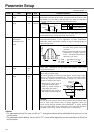
You can set up the frequency of the 1st resonance suppressing notch filter.
The notch filter function will be invalidated by setting up this parameter to
"1500".
1E 0 to 4
<2>
–1st notch width
selection
You can set up the notch filter width of the 1st resonance suppressing filter in 5 steps.
Higher the setup, larger the notch width you can obtain.
Use with default setup in normal operation.
Standard default : < >
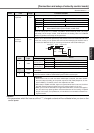
PrNo.
Setup
range
UnitTitle Function/Content
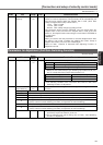
Parameters for Auto-Gain Tuning
20
0 to 10000
<250>*
%Inertia ratio
You can set up the ratio of the load inertia against the rotor (of the motor) inertia.
When you execute the normal auto-gain tuning, the load inertial will be
automatically estimated after the preset action, and this result will be
reflected in this parameter.
The inertia ratio will be estimated at all time while the real-time auto-gain
tuning is valid, and its result will be saved to EEPROM every 30 min.
<Caution>
If the inertia ratio is correctly set, the setup unit of Pr11 and Pr19
becomes (Hz). When the inertia ratio of Pr20 is larger than the actual, the
setup unit of the velocity loop gain becomes larger, and when the inertia
ratio of Pr20 is smaller than the actual, the setup unit of the velocity loop
gain becomes smaller.
Pr20=(load inertia/rotor inertia) X 100 [%]
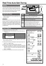
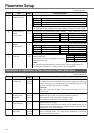
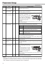
21 0 to 7
<1>
–Setup of real-time
auto-gain tuning
You can set up the action mode of the real-time auto-gain tuning.
With higher setup such as 3, the driver respond quickly to the change of
the inertia during operation, however it might cause an unstable operation.
Use 1for normal operation.
Setup value
0
<1>, 4, 7
2, 5
3, 6
Real-time
auto-gain tuning
Invalid
Normal mode
Varying degree of
load inertia in motion
–
Little change
Gradual change
Rapid change
Standard default : < >
PrNo.
Setup
range
UnitTitle Function/Content
<Notes>
•For parameters which No. have a suffix of "*", changed contents will be validated when you turn on the
control power.
• Parameters which default values have a suffix of "*" will be automatically set up during real time auto-gain
tuning. When you change manually, invalidate the real-time auto-gain tuning first then set, referring to
P.239, "Release of Automatic Gain Adjusting Function" of Adjustment.