


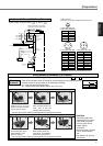

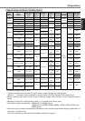
42
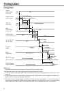
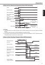
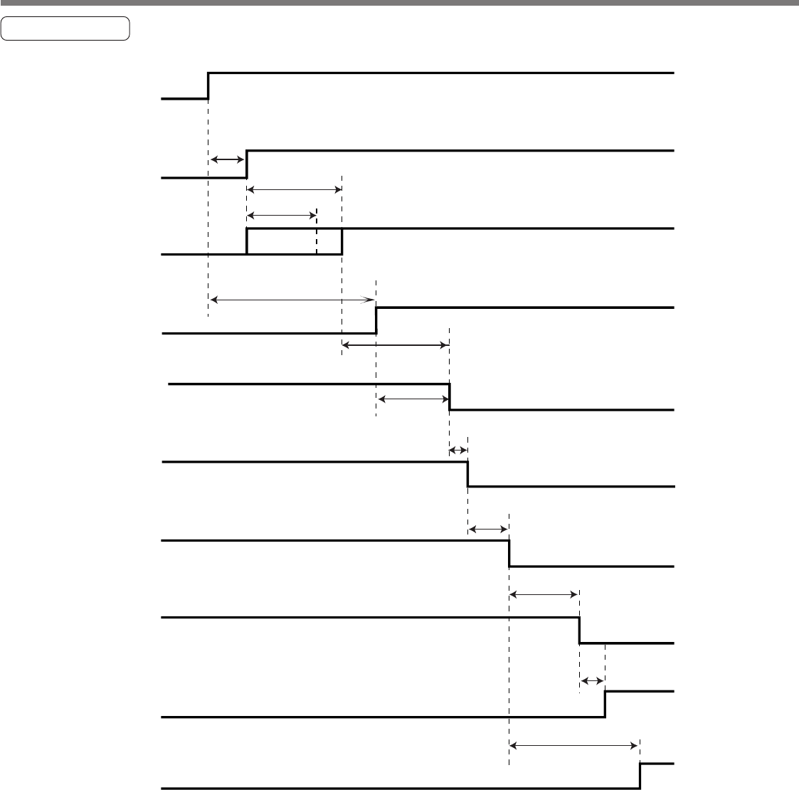
Timing Chart
<Cautions>
• The above chart shows the timing from AC power-ON to command input.
• Activate the external command input according to the above timing chart.
*1. In this term Servo-ON input (SRV-ON) turns ON as a hard ware, but operation command can not be
received.
*2. S-RDY output will turn on when both conditions are met, initialization of micro computer has been com-
pleted and the main power has been turned on.
*3. After Internal control power supply , protective functions are active from approx. 1.5 sec after the start of
initializing microcomputer. Please set the signals, especially for protective function, for example over-
travel inhibit input (CWL,CCWL) or external scale input, so as to decide their logic until this term.
Control
power supply
(L1C,L2C)
Internal control
power supply
Action of
driver CPU
Main
power supply
(L1,L2,L3)
S-RDY output
(X5, Pin-34 and 35)
Servo-ON input
(X5, Pin-29)
Dynamic
brake
Motor
energization
BRK-OFF output
(X5, Pin-10 and 11)
Position/Speed/
Torque command
10ms
or longer
*2
10ms
or longer
*2
OFF
OFF
ON
reset
(initialization)
usually operation
OFF ON
OFF ON
ONOFF
OFF (brake engaged) ON
(brake released)
releasedengaged
not-energized energized
No command entry Command
entry
100ms or longer
*1
approx.2s
approx.100 to 300 ms
approx.1.5s
established
approx.40ms
approx.2ms
approx.2ms
0ms or longer
0s or longer
*3
Timing Chart