93
[Connection and Setup of Position Control Mode]
Connection and Setup of
Position Control Mode
Output Signals (Pulse Train) and Their Functions
Title of signal
Pin No
Symbol Function
I/F circuit
PO1
P.85
A-phase output
B-phase output
Z-phase output
21
22
48
49
23
24
OA +
OA –
OB +
OB –
OZ +
OZ –
• Feeds out the divided encoder signal or external scale signal (A, B, Z-
phase) in differential. (equivalent to RS422)
• You can set up the division ratio with Pr44 (Numerator of pulse output
division) and Pr45 (Denominator of pulse output division)
• You can select the logic relation between A-phase and B-phase, and the
output source with Pr46 (Reversal of pulse output logic).
•
When the external scale is made as an output source, you can set up the
interval of Z-phase pulse output with Pr47 (Setup of external scale Z-phase).
• Ground for line driver of output circuit is connected to signal ground (GND)
and is not insulated.
• Max. output frequency is 4Mpps (after quadrupled)
Z-phase output 19 PO2
P.85
CZ
• Open collector output of Z-phase signal
• The emitter side of the transistor of the output circuit is connected to the
signal ground (GND) and is not insulated.
<Note>
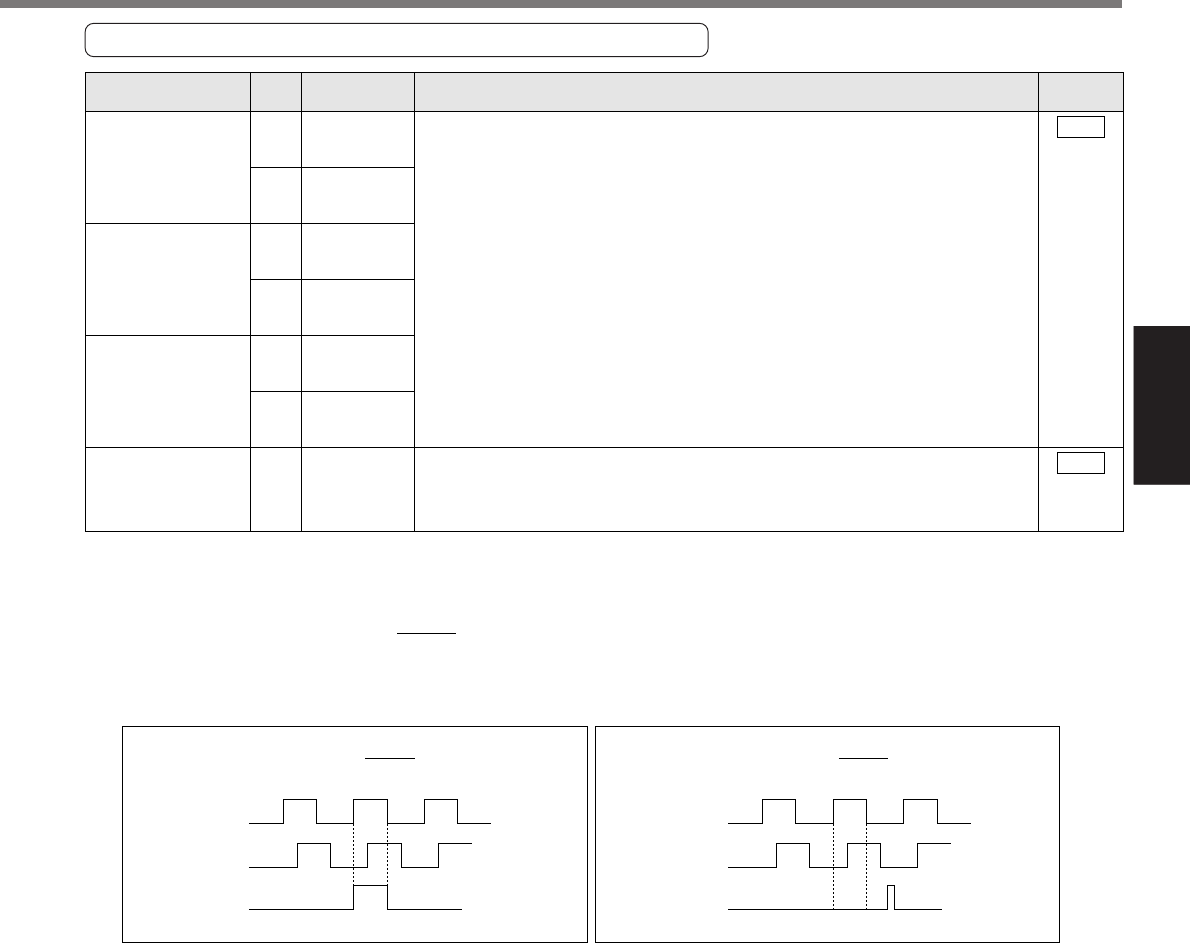
• When the output source is the encoder
• If the encoder resolution X is multiple of 4, Z-phase will be fed out synchronizing with A-phase.
In other case, the Z-phase width will be equal to the encoder resolution, and will not synchronize with
A-phase because of narrower width than that of A-phase.
• In case of the 5-wire, 2500P/r incremental encoder, the signal sequence might not follow the above fig.
until the first Z-phase is fed out. When you use the pulse output as the control signal, rotate the motor
one revolution or more to make sure that the Z-phase is fed out at least once before using.
Pr44
Pr45
A
B
Z
A
B
Z
synchronized
not-synchronized
Pr44
Pr45
when the encoder resolution is multiple of 4,
Pr44
Pr45
when the encoder resolution is not multiple of 4,


