


104
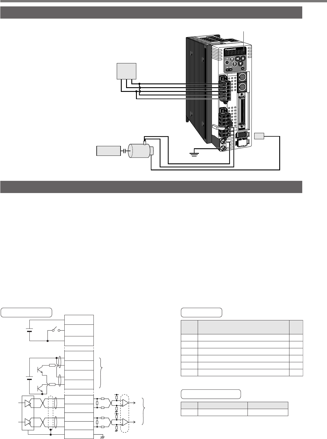
Trial Run (JOG run) at Position Control Mode
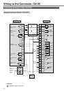
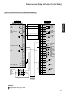
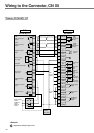
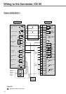
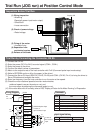
Trial Run by Connecting the Connector, CN X5
(1) Connect the CN X5.
(2) Enter the power (DC12 to 24V) to control signal (COM+, COM–)
(3) Enter the power to the driver.
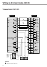
(4) Confirm the default values of parameters.
(5) Match to the output format of the host controller with Pr42 (Command pulse input mode setup).
(6) Write to EEPROM and turn off/on the power (of the driver).
(7) Connect the Servo-ON input (SRV-ON, CN X5, Pin-29) and COM– (CN X5, Pin-41) to bring the driver to
Servo-ON status and energize the motor.
(8) Enter low frequency from the host controller to run the motor at low speed.
(9) Check the motor rotational speed at monitor mode whether,
rotational speed is as per the setup or not, and
the motor stops by stopping the command (pulse) or not.
(10) If the motor does not run correctly, refer to P.68, "Display of Factor for No-Motor Running" of Preparation.
COM+
7
29
41
3
4
5
6
COM
-
SRV-ON
PULS1
PULS2
SIGN1
SIGN2
1kΩ
1kΩ
CW/CCW pulse input
in case of
open collector input
CN X5
in case of
line receiver
input
DC
12V – 24V
DC
12V
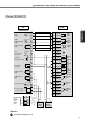
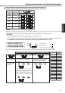
Title
Setup of control mode
Invalidation of over-travel inhibit input
Selection of command pulse input
Mode setup of command pulse input
Inhibition setup of command pulse input
Counter clear mode
Parameter
PrNo.
02
04
40
42
43
4E
Setup
value
0
1
0/1
1
1
2
Title of signal
Servo-ON
No.
0
Monitor display
+A
• Enter command pulses from the host controller.
43kΩ
2kΩ
2kΩ
43kΩ
SIGNH1
SIGNH2
PULSH1
PULS
H/L
PULSH2
44
45
SIGN
46
47
43kΩ
2kΩ
2kΩ
43kΩ
220Ω
220Ω
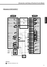
Wiring Diagram
Input signal status
GND
13
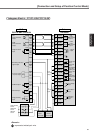
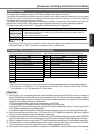
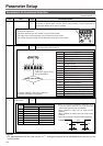
Inspection Before Trial Run
X3
X4
X5
X6
X7
Display LED
CN X6
ground
Power
supply
Motor
Machine
(1) Wiring inspection
• Miswiring
(Especially power input/motor output)
• Short/Earth
• Loose connection
(2) Check of power/voltage
• Rated voltage
(3) Fixing of the motor
• Unstable fixing
(4) Separation from
mechanical system
(5) Release of the brake