


299
[Supplement]
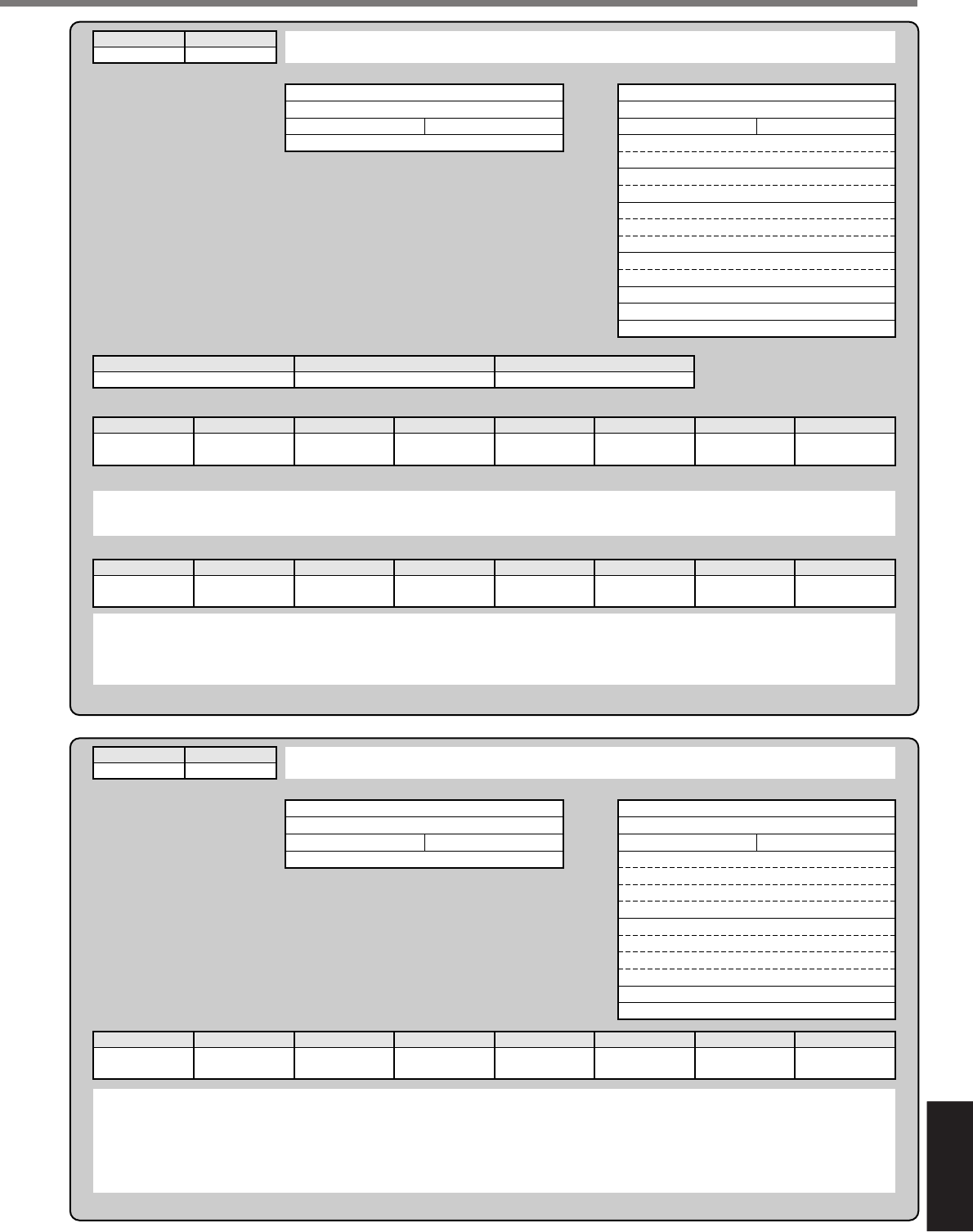
Supplement
command
2
mode
D
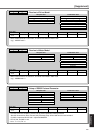
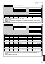
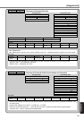
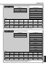
• Read out of Absolute Encoder
Reception data
0
axis
checksum
2D
Status (L)
Status (H)
Transmission data
• bit4 : System down
• bit5 : Battery alarm, multi-turn error, counter overflow, count error,full absolute status and logical sum of over speed
• Command error will occur when you use the above encoder or absolute encoder as an incremental encoder.
• Single turn data = 17bit (000000h to 01FFFFh)
• Multi-turn data = 16bit (0000h to FFFFh)
bit7
Battery alarm
6
System down
5
Multi-turn error
4
0
3
Counter
overflow
2
Count error
1
Full absolute
status
0
Over speed
Error code
bit7
0 : Normal
1 : Error
65
Command error
4
RS485 error
3210
0Bh
axis
encoder ID (L)
(H)
status (L)
(H)
(L)
single-turn data
(H)
multi-turn data (L)
(H)
0
Error code
checksum
2D
17bit absolute 3 11h
Encoder ID (L) Encoder ID (H)
command
2
mode
E
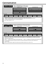
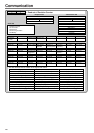
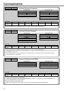
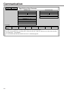
• Read out of External Scale Accumulation and Deviation
Reception data
2E
Error code
Transmission data
• External scale FB pulse sum will return the present position of the external scale counter in absolute coordinates from
the starting point.
• External scale FB pulse sum will be "-" for CW and "+" for CCW.
• External scale deviation becomes "+" when the external scale is positioned at CW direction against position
command, and "–" when it is positioned at CCW direction.
bit7
0 : Normal
1 : Error
654
RS485 errorCommand error
3210
0
axis
checksum
2E
9
axis
(L)
external scale
FB pulse sum
(H)
(L)
external scale deviation
(H)
error code
checksum