


95
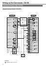
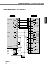
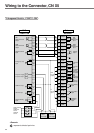
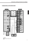
[Connection and Setup of Position Control Mode]
Connection and Setup of
Position Control Mode
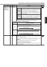
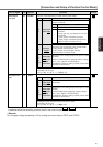
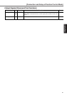
Output Signals (Others) and Their Functions
Title of signal
Pin No
Symbol Function
I/F circuit
Signal ground 13,15,
17,25
–
GND
• Signal ground
• This output is insulated from the control signal power (COM–) inside of the
driver.
Frame ground 50
–
FG • This output is connected to the earth terminal inside of the driver.