


216
Parameter Setup
<Notes>
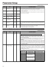
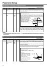
•For parameters which No. have a suffix of "*", changed contents will be validated when you turn on the
control power.
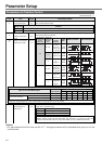
Parameters for Position Control
40
*
0 to 1
<0>
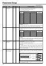
Selection of com-
mand pulse input
You can select either the photo-coupler input or the exclusive input for line driver as
the command pulse input.
Setup value
<0>
1
Content
Photo-coupler input (X5 PULS1:Pin-3, PULS2:Pin-4, SIGN1:Pin-5, SIGN2:Pin-6)
Exclusive input for line driver (X5 PULSH1:Pin-44, PULSH2:Pin-45, SIGNH1:Pin-46, SIGNH2:Pin-47)
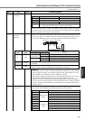
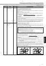
41
*
42
*
0 to 1
<0>
0 to 3
<1>
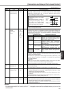
Command pulse
rotational direction
setup
Setup of command
pulse input mode
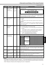
You can set up the rotational direction against the command pulse input, and the
command pulse input format.
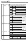
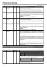
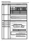
• Permissible max. input frequency, and min. necessary time width of command pulse input signal.
Pr41 setup value
(Command pulse
rotational
direction setup)
Pr42 setup value
(Command pulse
input mode
setup)
Signal
title
CCW command
B-phase advances to A by 90˚. B-phase delays from A by 90˚.
CW command
Command
pulse
format
t1
A-phase
B-phase
t1 t1 t1
t1 t1t1 t1
t2 t2
t2
t3
t2
t4
“H”
“L”
t5t4
t6 t6
t6 t6
t5
B-phase advances to A by 90˚.B-phase delays from A by 90˚.
t1
A-phase
B-phase
t1t1 t1
t1 t1 t1 t1
t2 t2
t2
t3
t2
t4
“L”
“H”
t5t4
t6 t6 t6 t6
t5
0 or 2
<0>
<1>
3
0 or 2
1
1
3
PULS
SIGN
PULS
SIGN
PULS
SIGN
PULS
SIGN
PULS
SIGN
PULS
SIGN
90˚ phase
difference
2-phase pulse
(A + B-phase)
CW pulse train
+
CCW pulse train
pulse train
+
Signal
90˚ phase
difference
2-phase pulse
(A + B-phase)
CW pulse train
+
CCW pulse train
pulse train
+
Signal
Line driver interface
Open collector interface
Pulse train interface exclusive to line driver
Pulse train interface
Input I/F of PULS/SIGN signal
Permissible max.
input frequency
2Mpps
500kpps
200kpps
t
1
500ns
2µs
5µs
Min. necessary time width
t
2
250ns
1µs
2.5µs
t
3
250ns
1µs
2.5µs
t
4
250ns
1µs
2.5µs
t
5
250ns
1µs
2.5µs
t
6
250ns
1µs
2.5µs
Make the rising/falling time of the command pulse input signal to 0.1µs or smaller.
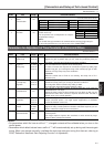
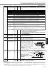
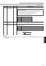
PrNo.
Setup
range
Title Function/Content
Standard default : < >
43 0 to 1
<1>
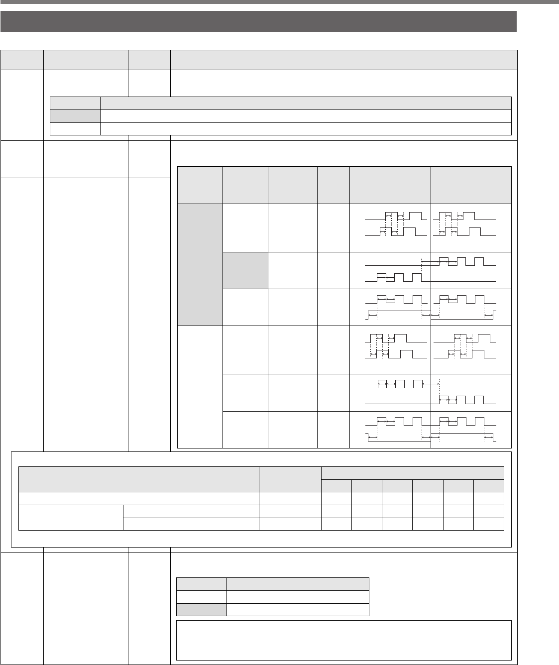
Invalidation of
command pulse
inhibit input
You can select either the validation or the invalidation of the command pulse inhibit
input (INH : CN X5 Pin-33).
Setup value
0
<1>
INH input
Valid
Invalid
Command pulse input will be inhibited by opening the connection of INH input to
COM–. When you do not use INH input, set up Pr43 to 1 so that you may not
need to connect INH (CN I/F Pin-33) and COM– (Pin-41) outside of the driver.