


254
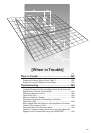
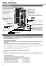
When in Trouble
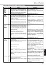
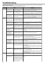
Protective
function
Causes Measures
Error
code No.
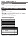
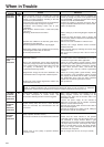
Over-load
protection
16
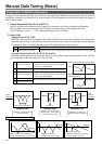
Torque command value has exceeded the over-load
level set with Pr72 (Setup of over-load level) and
resulted in overload protection according to the time
characteristics (described later)
1)Load was heavy and actual torque has exceeded the
rated torque and kept running for a long time.
2)Oscillation and hunching action due to poor
adjustment.
Motor vibration, abnormal noise. Inertia ratio (Pr20)
setup error.
3)Miswiring, disconnection of the motor.
4)Machine has collided or the load has gotten heavy.
Machine has been distorted.
5)Electromagnetic brake has been kept engaged.
6)While wiring multiple axes, miswiring has occurred by
connecting the motor cable to other axis.
7)Pr72 setup has been low.
Check that the torque (current) does not oscillates nor
fluctuate up an down very much on the graphic screen
of the PANATERM
®
. Check the over-load alarm display
and load factor with the PANATERM
®
.
1)I
ncrease the capacity of the driver and motor. Set up
longer acceleration/deceleration time. Lower the load.
2)Make a re-adjustment.
3)Make a wiring as per the wiring diagram. Replace the
cables.
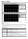
Connect the black (W phase), white (V phase) and
red (U phase) cables in sequence from the bottom at
the CN X2 connector.
4)Remove the cause of distortion. Lower the load.
5)Measure the voltage between brake terminals.
Release the brake
6)Make a correct wiring by matching the correct motor
and encoder wires.
7)Set up Pr72 to 0. (Set up to max. value of 115% of
the driver)
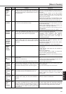
*Over-
regeneration
load
protection
18
Regenerative energy has exceeded the capacity of
regenerative resistor.
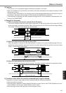
1)Due to the regenerative energy during deceleration
caused by a large load inertia, converter voltage has
risen, and the voltage is risen further due to the lack
of capacity of absorbing this energy of the
regeneration discharge resistor.
2)Regenerative energy has not been absorbed in the
specified time due to a high motor rotational speed.
3)Active limit of the external regenerative resistor has
been limited to 10% duty.
Check the load factor of the regenerative resistor on
the monitor screen of the PANATERM
®.
Do not use in
the continuous regenerative brake application.
1)Check the running pattern (velocity monitor). Check
the load factor of the regenerative resistor and over-
regeneration warning display. Increase the capacity
of the driver and the motor, and loosen the
deceleration time. Use the external regenerative
resistor.
2)Check the running pattern (speed monitor). Check
the load factor of the regenerative resistor. Increase
the capacity of the driver and the motor, and loosen
the deceleration time. Lower the motor rotational
speed. Use an external regenerative resistor.
3)Set up Pr6C to 2.
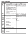
Position
deviation
excess
protection
24
Deviation pulses have exceeded the setup of Pr70
(Setup of position deviation excess).
1)The motor movement has not followed the command.
2)Setup value of Pr70 (Setup of position deviation
excess) is small.
1)Check that the motor follows to the position
command pulses. Check that the output toque has
not saturated in torque monitor. Make a gain
adjustment. Set up maximum value to Pr5E (Setup of
1st torque limit) and Pr5F (2nd torque limit setup).
Make a encoder wiring as per the wiring diagram.
Set up the longer acceleration/deceleration time.
Lower the load and speed.
2)Set up a larger value to Pr70, or set up 0 (invalid).
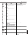
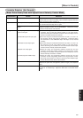
*Encoder
communi-
cation error
protection
21
Communication between the encoder and the driver
has been interrupted in certain times, and
disconnection detecting function has been triggered.
• Make a wiring connection of the encoder as per the
wiring diagram. Correct the miswiring of the
connector pins. Note that the encoder cable to be
connected to CN X6.
• Secure the power supply for the encoder of
DC5V±5% (4.75-5.25V)...pay an attention especially
when the encoder cables are long.
• Separate the encoder cable and the motor cable if
they are bound together.
• Connect the shield to FG...Refer to P.38, "Wiring to
the Connector, CN X6" of Preparation.
*Encoder
communi-
cation
data error
protection
23
Communication error has occurred in data from the
encoder. Mainly data error due to noise. Encoder
cables are connected, but communication data has
some errors.
<Remarks>
Install an external protection such as thermal fuse without fail when you set up Pr6C to 2. Otherwise,
regenerative resistor loses the protection and it may be heated up extremely and may burn out.