


175
[Connection and Setup of Torque Control Mode]
Connection and Setup of
Torque Control Mode
04
*
0 to 2
<1>
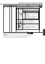
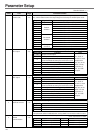
Setup of
over-travel
inhibit input
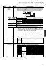
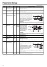
In linear drive application, you can use this over-travel inhibiting function to inhibit the
motor to run to the direction specified by limit switches which are installed at both ends
of the axis, so that you can prevent the work load from damaging the machine due to
the over-travel. With this input, you can set up the action of over-travel inhibit input.
<Cautions>
1. When Pr04 is set to 0 and over-travel inhibit input is entered, the motor deceler-
ates and stops according to the preset sequence with Pr66 (Sequence at over-
travel inhibition). For details, refer to the explanation of Pr66.
2. When both of CCWL and CWL inputs are opened while Pr04 is set to 0, the driver
trips with Err38 (Overtravel inhibit input error) judging that this is an error.
3. When you turn off the limit switch on upper side of the work at vertical axis applica-
tion, the work may repeat up/down movement because of the loosing of upward
torque. In this case, set up Pr66 to 2, or limit with the host controller instead of us-
ing this function.
CW direction CCW direction
CCWL
CWL
Work
Servo motor
Limit
switch
Limit
switch
Driver
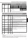
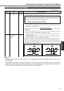
Setup
value
0
<1>
2
Action
CCWL/CWL
input
Valid
Invalid
Valid
Input
CCWL
(CN X5,Pin-9)
CWL
(CN X5,Pin-9)
Connection to COM–
Close
Open
Close
Open
Normal status while CCW-side limit switch is not activated.
Inhibits CCW direction, permits CW direction.
Normal status while CW-side limit switch is not activated.
Inhibits CW direction, CCW direction permitted.
Both CCWL and CWL inputs will be ignored, and over-travel inhibit function will be
invalidated.
Err38 (Over-travel inhibit input protection) is triggered when either one
of the connection of CW or CCW inhibit input to COM– become open.
PrNo.
Setup
range
Title Function/Content
Standard default : < >
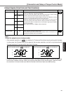
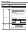
06 0 to 2
<0>
Selection of
ZEROSPD input
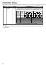
You can set up the function of the speed zero clamp input (ZEROSPD : CN X5, Pin-26)
Setup value
<0>, 2
1
Function of ZEROSPD (Pin-26)
ZEROSPD input is ignored and the driver judge that it Is not in
speed zero clamp status.
ZEROSPD input becomes valid. Speed command is taken as 0 by
opening the connection to COM–.
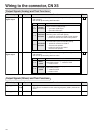
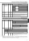
07 0 to 9
<3>
Selection of speed
monitor (SP)
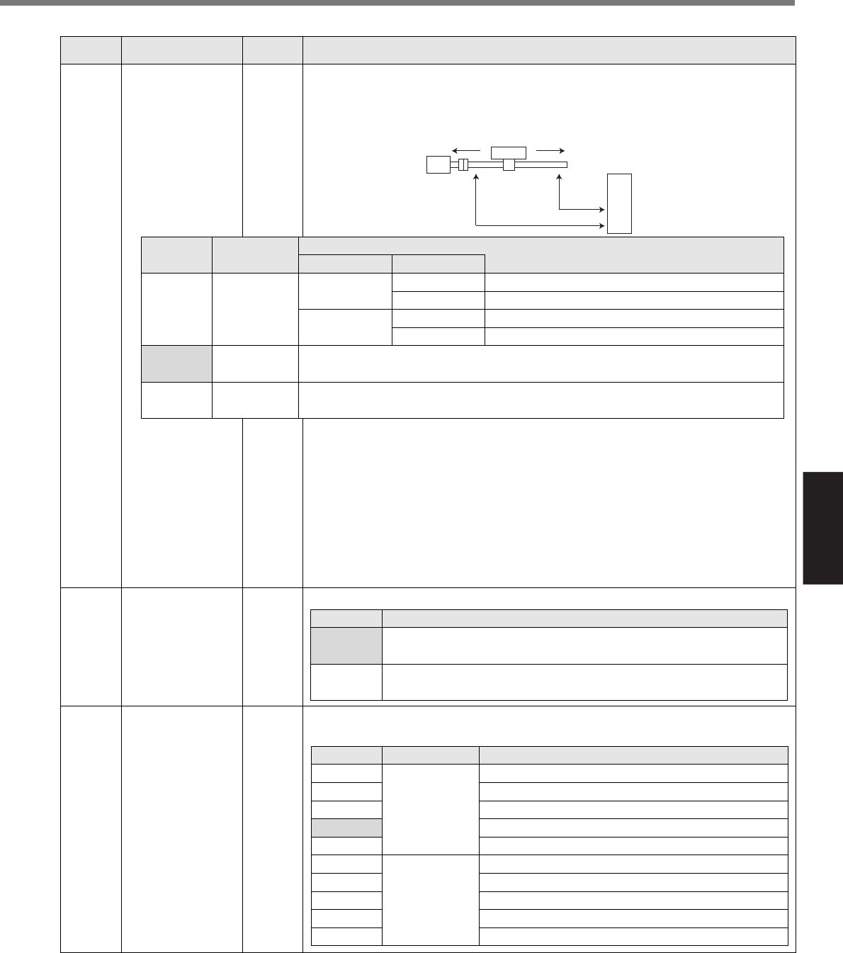
You can set up the content of analog speed monitor signal output (SP : CN X5,
Pin43) and the relation between the output voltage level and the speed.
Setup value
0
1
2
<3>
4
5
6
7
8
9
Signal of SP
Motor actual
speed
Command
speed
Relation between the output voltage level and the speed
6V / 47 r/min
6V / 188 r/min
6V / 750 r/min
6V / 3000 r/min
1.5V / 3000 r/min
6V / 47 r/min
6V / 188 r/min
6V / 750 r/min
6V / 3000 r/min
1.5V / 3000 r/min