


133
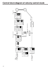
[Connection and setup of velocity control mode]
Connection and Setup of
Velocity Control Mode
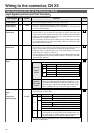
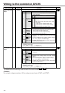
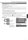
Input Signals (Analog Command) and Their Functions
Title of signal
Pin No.
Symbol Function
I/F circuit
Speed command
input
14 AI
P.128
SPR
• Function varies depending on control mode.
•The resolution of the A/D converter used in this input is 16 bit
(including 1 bit for sign).
± 32767 (LSB) = ± 10[V], 1[LSB]
.
=
.
0.3[mV]
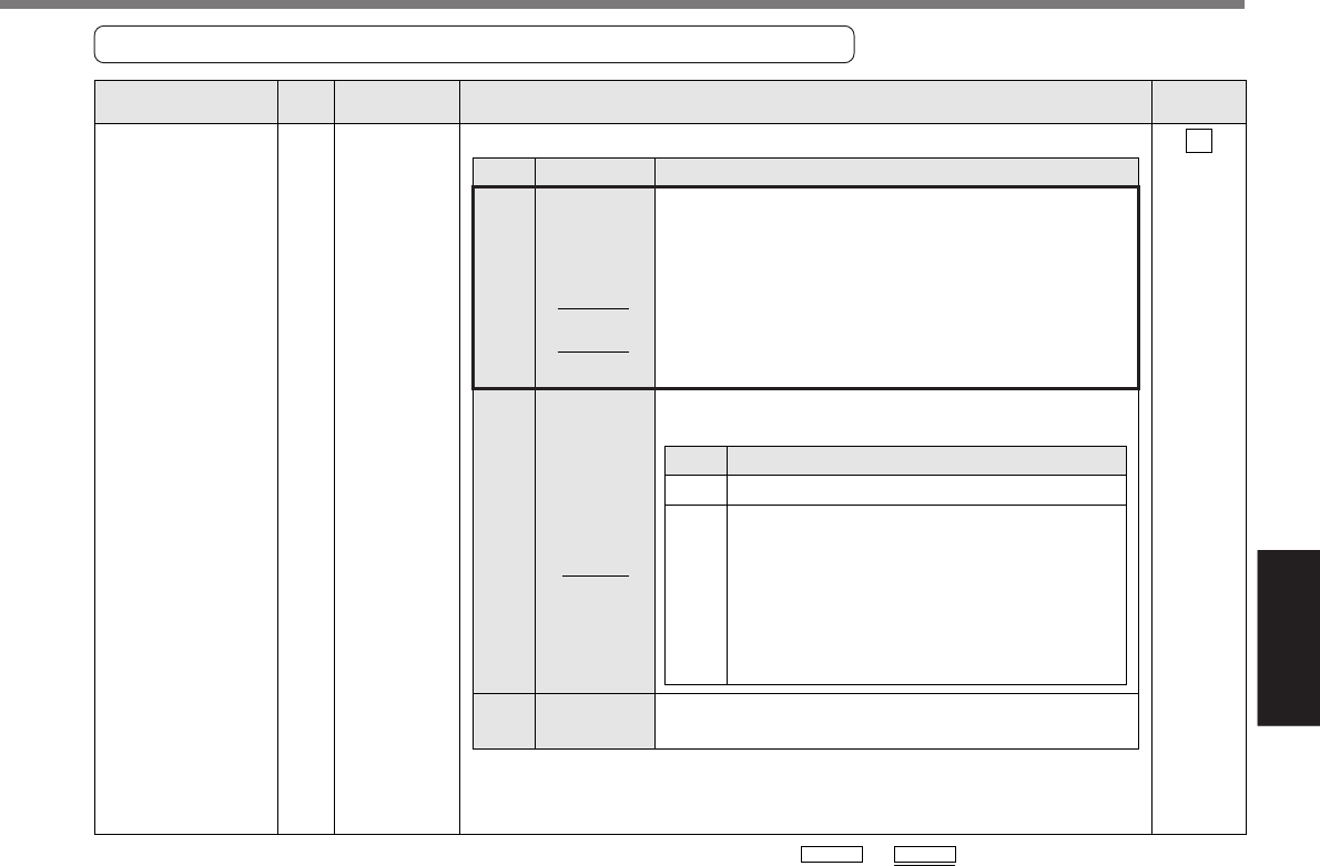
Velocity
control
Position/
Velocity
Velocity/
Torque
Control mode
Velocity/
Torque
Other control
mode
Function
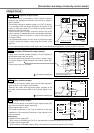
• Input of external speed command (SPR) when the
velocity control is selected.
• Set up the gain, polarity, offset and filter of the
Speed command with;
Pr50 (Speed command input gain)
Pr51 (Speed command input reversal)
Pr52 (Speed command offset)
Pr57 (Speed command filter setup)
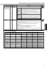
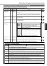
• Function varies depending on Pr5B (Selection of
torque command)
• This input is invalid.
Pr5B
0
1
Pr02
Others
Content
• This input becomes invalid.
• Speed limit (SPL) will be selected.
• Set up the speed limit (SPL) gain, offset
and filter with;
Pr50 (Speed command input gain)
Pr52 (Speed command offset)
Pr57 (Speed command filter setup)
1
3
5
5
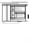
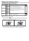
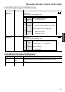
*Function becomes valid when the control mode with underline ( / )
is selected while the switching mode is used in the control mode in table.
<Remark>
Do not apply voltage exceeding ±10V to analog command input of SPR