


200
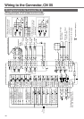
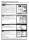
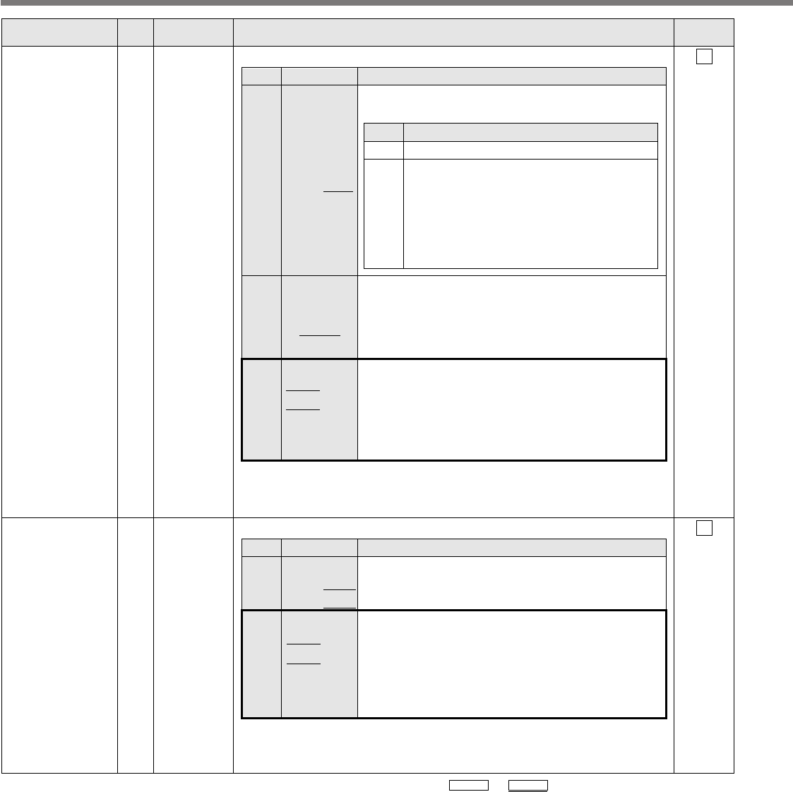
Wiring to the Connector, CN X5
Title of signal
Pin No.
Symbol Function
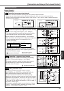
I/F circuit
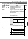
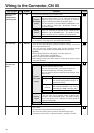
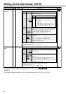
CCW-Torque
limit input
16 AI
P.193
CCWTL • Function varies depending on Pr02 (Control mode setup).
• Resolution of A/D converter used in this input is 16 bit
(including 1 bit for sign).
± 511 [LSB] = ± 11.9[V], 1 [LSB]
.
=
.
23[mV]
Control mode
Torque Control
Position/Torque
Velocity/
Torque
Position/Torque
Velocity/Torque
Other
control mode
Function
• Function varies depending on Pr5B (Selection of
torque command)
Pr5B
0
1
This input becomes invalid.
• Torque command input (TRQR) will be
selected.
• Set up the gain and polarity of the com-
mand with;
Pr5C (Torque command input gain)
Pr5D (Torque command input reversal)
• Offset and filter cannot be set up.
Content
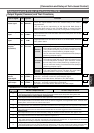
Pr02
2
4
5
4
5
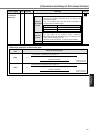
Other
• Becomes to the torque command input (TRQR).
• Set up the gain and polarity of the command with;
Pr5C (Torque command input gain)
Pr5D (Torque command input reversal)
• Offset and filter cannot be set up.
• Becomes to the analog torque limit input to CCW
(CCWTL).
• Limit the CCW-torque by applying positive voltage
(0 to +10V) (Approx.+3V/rated toque)
• Invalidate this input by setting up Pr03 (Torque limit
selection) to other than 0.
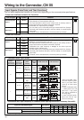
CW-Torque limit
input
18 AI
P.193
CWTL
• Function varies depending on Pr02 (Control mode setup).
• Resolution of A/D converter used in this input is 16 bit
(including 1 bit for sign).
± 511 [LSB] = ± 11.9[V], 1 [LSB]
.
=
.
23[mV]
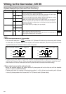
Control mode
Torque control
Position/Torque
Velocity/Torque
Position/Torque
Velocity/Torque
Other
control mode
Function
• This input becomes invalid when the torque control
is selected.
• Becomes to the analog torque limit input to CW
(CWTL).
• Limit the CW-torque by applying negative voltage
(0 – -10V) (Approx.+3V/rated toque).
Invalidate this input by setting up Pr03 (Torque limit
selection) to other than 0.
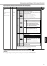
Pr02
2
4
5
4
5
Other
*Function becomes valid when the control mode with underline ( / )
is selected while the switching mode is used in the control mode in table.
<Remark>
Do not apply voltage exceeding ±10V to analog command input of CWTL and CCWTL.