


253
[When in Trouble]
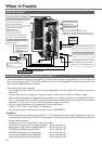
When in Trouble
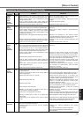
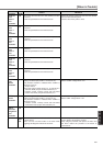
Protective Function (Detail of Error Code)
Protective
function
Causes Measures
Error
code No.
Voltage between P and N of the converter portion of the
control power supply has fallen below the specified value.
1)Power supply voltage is low. Instantaneous power
failure has occurred
2)
Lack of power capacity...Power supply voltage has
fallen down due to inrush current at the main power-on.
3)Failure of servo driver (failure of the circuit)
Measure the voltage between lines of connector (L1C
and L2C) and terminal block (r and t).
1)Increase the power capacity. Change the power
supply.
2)Increase the power capacity.
3)Replace the driver with a new one.
Control
power
supply
under-
voltage
protection
11
Over-
voltage
protection
12
Voltage between P and N of the converter portion of the
control power supply has exceeded the specified value
1)Power supply voltage has exceeded the permissible
input voltage. Voltage surge due to the phase-
advancing capacitor or UPS (Uninterruptible Power
Supply) have occurred.
2)Disconnection of the regeneration discharge resistor
3)External regeneration discharge resistor is not appro-
priate and could not absorb the regeneration energy.
4)Failure of servo driver (failure of the circuit)
Measure the voltage between lines of connector (L1,
L2 and L3).
1)Enter correct voltage. Remove a phase-advancing
capacitor.
2)Measure the resistance of the external resistor
connected between terminal P and B of the driver.
Replace the external resistor if the value is ∞.
3)Change to the one with specified resistance and
wattage.
4)Replace the driver with a new one.
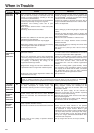
Main power
supply
under-
voltage
protection
13
Instantaneous power failure has occurred between L1 and
L3 for longer period than the preset time with Pr6D (Main
power off detecting time) while Pr65 (LV trip selection at
the main power-off) is set to 1. Or the voltage between P
and N of the converter portion of the main power supply
has fallen below the specified value during Servo-ON.
1)Power supply voltage is low. Instantaneous power
failure has occurred
2)Instantaneous power failure has occurred.
3)Lack of power capacity...Power supply voltage has
fallen down due to inrush current at the main power-
on.
4)Phase lack...3-phase input driver has been operated
with single phase input.
5)Failure of servo driver (failure of the circuit)
Measure the voltage between lines of connector (L1,
L2 and L3).
1)
Increase the power capacity. Change the power supply.
Remove the causes of the shutdown of the magnetic
contactor or the main power supply, then re-enter the power.
2)
Set up the longer time to Pr6D (Main power off detecting
time). Set up each phase of the power correctly.
3)Increase the power capacity. For the capacity, refer
to P.32, "Driver and List of Applicable Peripheral
Equipments" of Preparation.
4)Connect each phase of the power supply (L1, L2 and
L3) correctly. For single phase, 100V and 200V
driver, use L1 and L3.
5)Replace the driver with a new one.
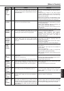
*Over-
current
protection
14
Current through the converter portion has exceeded
the specified value.
1)Failure of servo driver (failure of the circuit, IGBT or
other components)
2)Short of the motor wire (U, V and W)
3)Earth fault of the motor wire
4)Burnout of the motor
5)Poor contact of the motor wire.
6)Melting of the relays for dynamic brake due to
frequent Servo-ON/OFF operation
7)The motor is not applicable to the driver.
8)Timing of pulse input is same as or earlier than
Servo-ON.
9)Overheating of the dynamic brake circuit (F-frame
only)
1)Turn to Servo-ON, while disconnecting the motor. If
error occurs immediately, replace with a new driver.
2)Check that the motor wire (U, V and W) is not
shorted, and check the branched out wire out of the
connector. Make a correct wiring connection.
3)Measure the insulation resistance between motor
wires, U, V and W and earth wire. In case of poor
insulation, replace the motor.
4)Check the balance of resister between each motor
line, and if unbalance is found, replace the motor.
5)Check the loose connectors. If they are, or pulled
out, fix them securely.
6)Replace the driver. Prohibit the run/stop operation
with Servo-ON/OFF.
7)
Check the name plate and capacity of the motor and
driver, and replace with motor applicable to the driver.
8)Enter the pulses 100ms or longer after Servo-ON.
9)
Discontinue the run/stop operation with Servo ON-OFF.
Allow approx. 3 minutes pause when the dynamic
brake is activated during high-speed running.
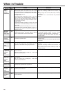
*Over-heat
protection
15
Temperature of the heat sink or power device has been
risen over the specified temperature.
1)Ambient temperature has risen over the specified
temperature.
2)Over-load
1)Improve the ambient temperature and cooling
condition.
2)Increase the capacity of the driver and motor.
Set up longer acceleration/deceleration time.
Lower the load.