


261
[When in Trouble]
When in Trouble
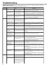
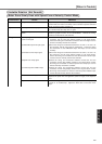
Unstable Rotation (Not Smooth)
Motor Runs Slowly Even with Speed Zero at Velocity Control Mode
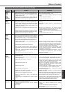
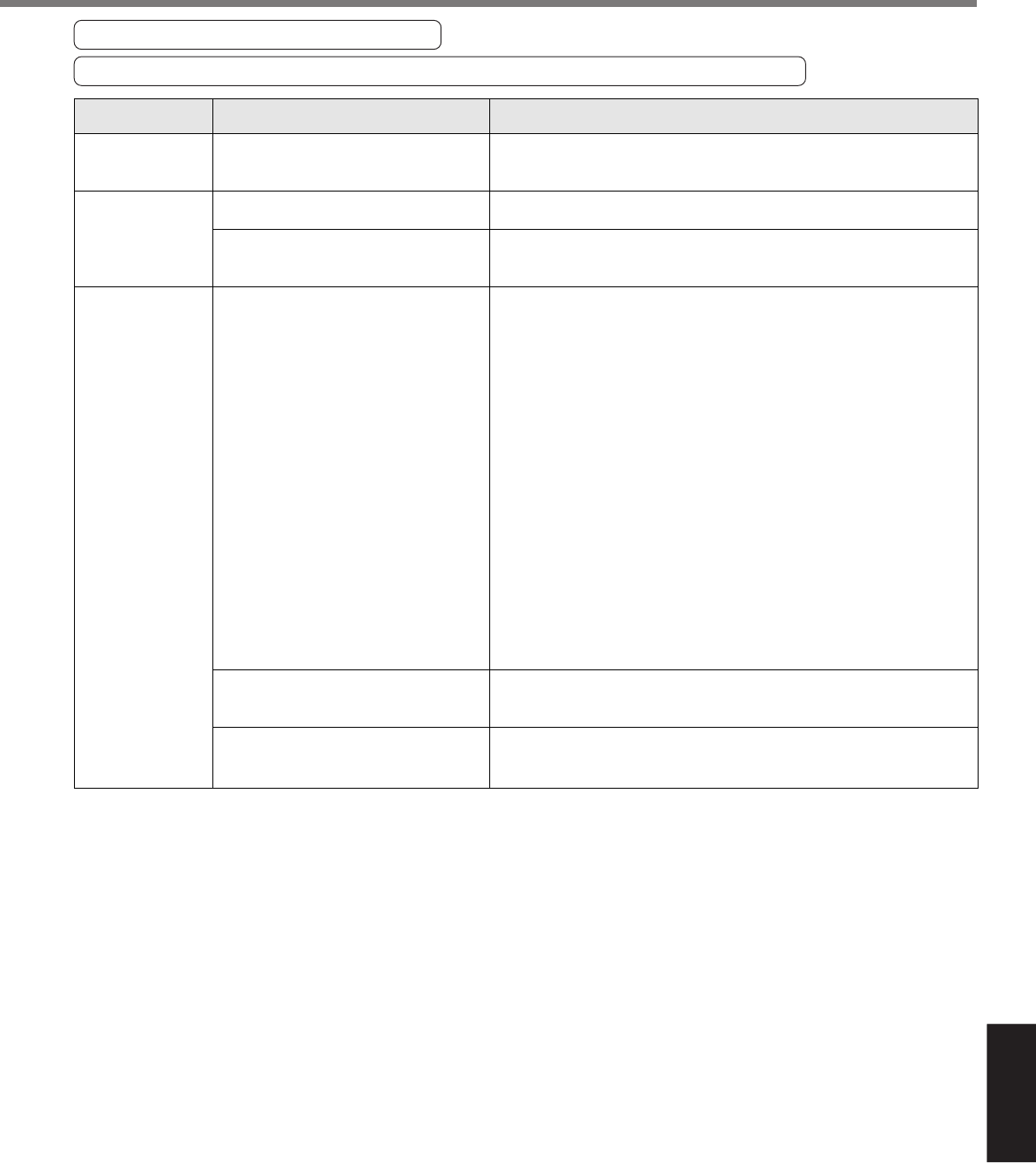
Classification Causes Measures
Setup of the control mode is not correct.
Gain adjustment is not proper.
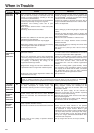
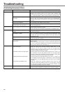
Velocity and position command are not
stable.
Each input signal of CN X5 is chattering.
1) Servo-ON signal
2) CW/CCW torque limit input signal
3) Deviation counter input signal
4) Speed zero clamp signal
5) Command pulse inhibition input
Noise is on the velocity command.
Slip of offset
If you set up Pr02 to 1(Velocity control mode) by mistake at position
control mode, the motor runs slowly at servo-ON due to speed command
offset. Change the setup of Pr02 to 0.
Increase the setup of Pr11, 1st velocity loop gain. Enter torque filter of
Pr14 and increase the setup of Pr11 again.
Check the motor movement with check pin of the front panel or the
waveform graphic function of the PANATERM
®
. Review the wiring,
connector contact failure and controller.
1)Check the wiring and connection between Pin29 and 41 of the
connector, CN X5 using the display function of I/O signal status.
Correct the wiring and connection so that the Servo-ON signal can be
turned on normally. Review the controller.
2)Check the wiring and connection between Pin-18 and 17, 16 and 17 of
the connector, CN X5 using tester or oscilloscope. Correct the wiring
and connection so that CW/CCW torque limit input can be entered
normally.
3)Check the wiring and connection between Pin-30 and 41, 16 and 17 of
the connector, CN X5 using display function of I/O signal status.
Correct the wiring and connection so that the deviation counter input
can be turned on normally. Review the controller.
4)Check the wiring and connection between Pin-26 and 41of the
connector, CN X5 using Display function of I/O signal status. Correct
the wiring and connection so that the speed zero clamp input can be
entered normally. Review the controller.
5)Check the wiring and connection between Pin-33 and 41of the
connector, CN X5 using display function of I/O signal status. Correct
the wiring and connection so that the command pulse inhibition input
can be entered normally. Review the controller.
Use a shield cable for connecting cable to the connector, CN X5.
Separate the power line and signal line (30cm or longer) in the separate
duct.
Check the voltage between Pin-14 and 15 (speed command input) using
a tester or an oscilloscope. Adjust the Pr52 value so that the motor
stops.
Parameter
Adjustment
Wiring