


161
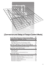
Connection and Setup of
Torque Control Mode
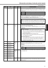
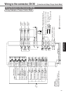
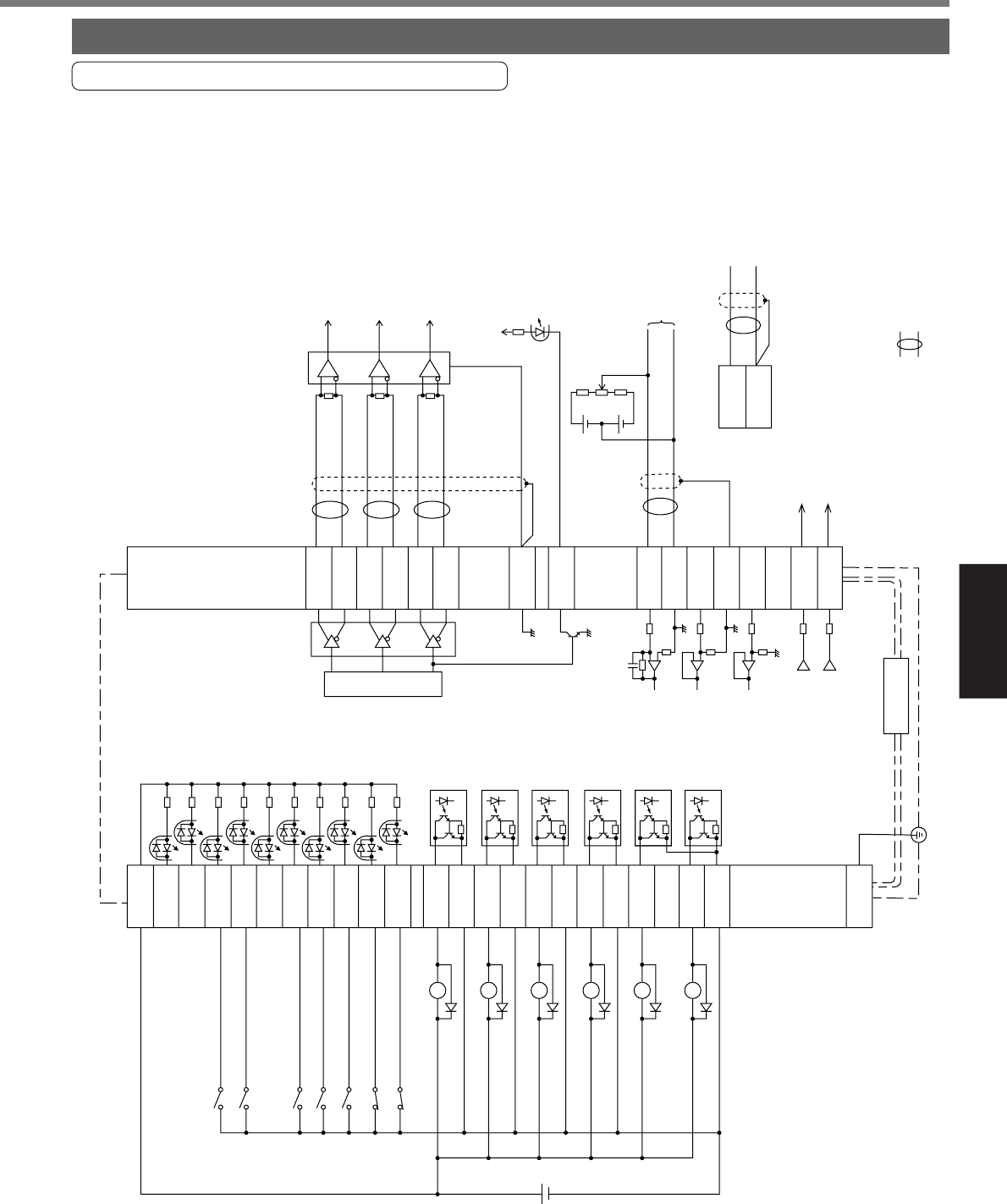
Wiring Example to the Connector CN X5
Wiring Example of Torque Control Mode
Wiring to the connector, CN X5
7
4.7kΩ
COM+
OA+
OA
-
OB+
OB
-
OZ+
OZ
-
GND
CZ
SPR/TRQR
GND
CCWTL/TRQR
GND
CWTL
SP
IM
21
22
48
24
25
19
14
15
16
17
43
18
42
49
23
3.83kΩ
3.83kΩ
20kΩ
10kΩ
10kΩ
1kΩ
1kΩ
INH
CL
SRV-ON
GAIN
DIV
ZEROSPD
C-MODE
A-CLR
CCWL
CWL
S-RDY+
S-RDY
-
ALM+
AT-SPEED
+
BRKOFF
+
BRKOFF
-
TLC
ZSP
COM
-
FG
AT-SPEED
-
ALM
-
33
30
29
27
28
26
32
31
9
8
35
34
37
36
39
38
11
10
40
12
41
50
Servo-ON input
Gain switching input
Divider
Alarm clear input
Torque command input or
velocity limit input (0 to ±10V)
Velocity monitor output
Torque monitor output
Z-phase output (open collector)
Servo-Ready output
Servo-Alarm output
At-speed signal output
Brake release output
Torque in-limit output
(Select with Pr09)
Zero speed detection output
(Select with Pr0A)
Wiring example when control mode Pr02=0 or Pr5B=1,
CCWTL/TRQR
GND
16
17
CW torque limit input
(0 to ±10V)
330Ω
330Ω
330Ω
Speed zero clamp
input
CN X5
<Remarks>
In case Pr5B=0,
enter a speed limit value to
4th speed of speed setup (Pr56).
Control mode
switching input
CCW over-travel
inhibition input
CW over-travel
inhibition input
V
DC
12
to
24V
A-phase
output
B-phase
output
Z-phase
output
( represents twisted pair.)
Select with Pr5B.
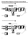
[Connection and Setup of Torque Control Mode]