


83
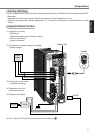
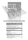
Connection and Setup of
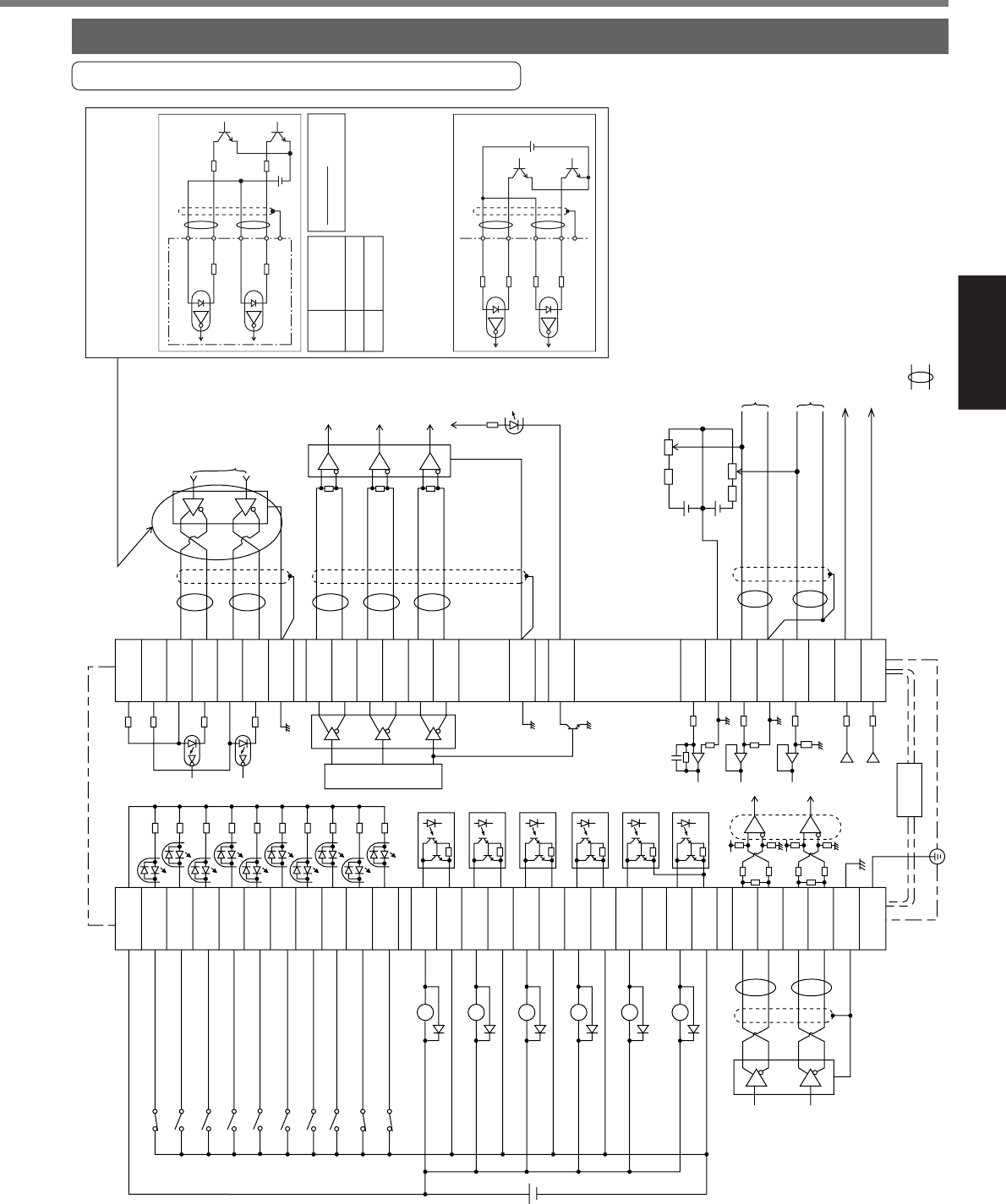
Position Control Mode
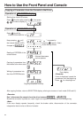
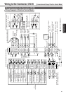
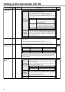
Wiring Example to the Connector, CN X5
Wiring Example of Position Control Mode
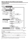
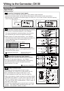
Wiring to the Connector, CN X5
14
15
16
43
18
42
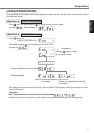
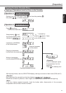
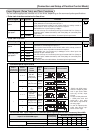
In case of open collector I/F
(1) When you use the external
resistor with 12V and 24V
power supply
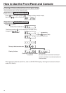
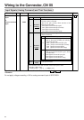
(2) When you do not use the
external resistor with 24V
power supply
CCW torque limit input
(0 to +10V)
CW torque limit input
(
-
10 to +10V)
Velocity monitor output
Torque monitor output
( represents twisted pair.)
Command
pulse
input A
(Use with 500kpps
or less.)
7
4.7kΩ
COM+
PULS2
SIGN1
SIGN2
GND
OA+
OA
-
OB+
OB
-
OZ+
OZ
-
GND
CZ
SPR/TRQR
GND
CCWTL/TRQR
GND
CWTL
SP
IM
3
2
1
4
5
6
13
21
22
48
24
25
19
49
23
3.83kΩ
3.83kΩ
43kΩ
2kΩ
2kΩ
43kΩ
220Ω
20kΩ
220Ω
330Ω
330Ω
330Ω
220Ω
2.2kΩ
2.2kΩ
10kΩ
10kΩ
1kΩ
1kΩ
PULS1
OPC2
OPC1
INH
CL
SRV-ON
GAIN
DIV
VS-SEL
C-MODE
A-CLR
CCWL
CWL
S-RD Y
+
S-RDY
-
ALM+
COIN+
BRKOFF
+
BRKOFF
-
TLC
V
DC
12 to
24V
ZSP
COM
-
SIGNH1
SIGNH2
GND
PULSH1
PULS
PULSH2
FG
COIN
-
ALM
-
33
30
29
27
28
32
31
9
8
35
34
37
36
39
38
11
10
40
12
41
44
45
13
50
Servo-ON input
Gain switching input
Electronic gear
switching input
Control mode
switching input
26
Damping control
switching input
Divider
Alarm clear input
CCW over-travel
inhibition input
A-phase
output
B-phase
output
Z-phase
output
Z-phase output (open collector)
CW over-travel
inhibition input
Servo-Ready output
Servo-Alarm output
Positioning complete output
Brake release output
Torque in-limit output
(Select with Pr09)
Zero speed detection output
(Select with Pr0A)
Deviation counter
clear input
Command pulse
inhibition input
Command pulse input B
(Use with 2Mpps or less.)
PULS1
PULS2
SIGN1
GND
V
DC
12V
24V
Specifications
of R
1kΩ1/2W
2kΩ1/2W
SIGN2
220Ω
220Ω
V
DC
R
R
3
4
5
6
13
PULS2
GND
SIGN2
OPC1
OPC2
220Ω
220Ω
24V
DC
1
4
2
6
13
2.2kΩ
2.2kΩ
V
DC
-
1.5
R
+
220
=10mA
.
.
CN X5
SIGN
46
47
43kΩ
2kΩ
2kΩ
43kΩ
220Ω
[Connection and Setup of Position Control Mode]