


207
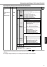
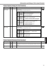
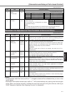
[Connection and Setup of Full-closed Control]
Full-Closed
Control Mode
PrNo.
10
11
12
13
14
18
19
1A
1B
1C
20
2F
Title
1st gain of position loop
1st gain of velocity loop
1st time constant of velocity loop integration
1st filter of velocity detection
1st time constant of torque filter
2nd gain of position loop
2nd gain of velocity loop
2nd time constant of velocity loop integration
2nd filter of speed detection
2nd time constant of torque filter
Inertia ratio
Adaptive filter frequency
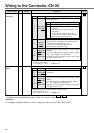
PrNo.
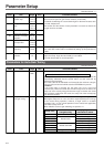
15
16
27
30
31
32
33
34
35
36
300
50
0
1
10
30
50
33
20
0
Title Setup value
Velocity feed forward
Time constant of feed forward filter
Setup of instantaneous speed observer
2nd gain setup
1st mode of control switching
1st delay time of control switching
1st level of control switching
1st hysteresis of control switching
Position gain switching time
2nd mode of control switching
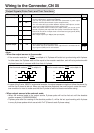
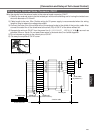
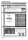
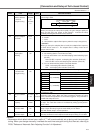
Resonance point
Command pattern
Load
Conditions which obstruct adaptive filter action
• When resonance frequency is lower than 300[Hz].
• While resonance peak is low or control gain is small and when no affect from these condition is
given to the motor speed.
• When multiple resonance points exist.
•
When the motor speed variation with high frequency factor is generated due to non-linear factor such as backlash.
• When acceleration/deceleration is very extreme such as more than 30000 [r/min] per 1 [s].
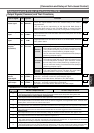
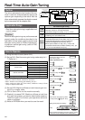
Adaptive Filters
The adaptive filter is validated by setting up Pr23 (Setup of adaptive filter mode) to other than 0.
The adaptive filter automatically estimates a resonance frequency out of vibration component presented in the motor speed
in motion, then removes the resonance components from the torque command by setting up the notch filter coefficient
automatically, hence reduces the resonance vibration.
The adaptive filter may not operate property under the following conditions. In these cases, use 1st notch filter (Pr1D and 1E)
and 2nd notch filter (Pr28-2A) to make measures against resonance according to the manual adjusting procedures.
For details of notch filters, refer to P.246, "Suppression of Machine Resonance" of Adjustment.
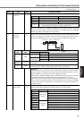
Parameters Which Are Automatically Set Up.
Following parameters are automatically adjusted.
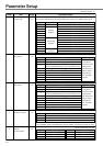
Also following parameters are automatically set up.
<Notes>
• When the real-time auto-gain tuning is valid, you cannot change parameters which are automatically adjusted.
• Pr31 becomes 10 at position or full closed control and when Pr21 (Setup of Real-Time Auto-Gain
Tuning Mode) is 1 to 6, and becomes 0 in other cases.
<Note>
Even though Pr23 is set up to other than 0, there are other cases when adaptive filter is automatically
invalidated. Refer to P.235, "Invalidation of adaptive filter" of Adjustment.
Cautions
(1) After the start-up, you may experience abnormal noise and oscillation right after the first Servo-ON, or when you increase the
setup of Pr22 (Selection of machine stiffness at real-time auto-gain tuning), until load inertia is identified (estimated) or adaptive
filter is stabilized, however, these are not failures as long as they disappear immediately. If they persist over 3 reciprocating
operations, take the following measures in possible order.
1) Write the parameters which have given the normal operation into EEPROM.
2) Lower the setup of Pr22 (Selection of machine stiffness at real-time auto-gain tuning).
3) Set up both Pr21 (Setup of real-time auto-gain tuning) and Pr23 (Setup of adaptive filter mode) to 0, then set up other value
than 0. (Reset of inertia estimation and adaptive action)
4) Invalidate the adaptive filter by setting up Pr23 (Setup of adaptive filter mode setup) to 0, and set up notch filter manually.
(2) When abnormal noise and oscillation occur, Pr20 (Inertia ratio) or Pr2F (Adaptive filter frequency) might have changed to
extreme values. Take the same measures as the above in these cases.
(3) Among the results of real-time auto-gain tuning, Pr20 (Inertia ratio) and Pr2F (Adaptive filter frequency) will be written to EEPROM
every 30 minutes. When you turn on the power again, auto-gain tuning will be executed using the latest data as initial values.
(4)
When you validate the real-time auto-gain tuning, Pr27 (Setup of instantaneous speed observer) will be invalidated automatically.
(5) The adaptive filter is normally invalidated at torque control, however, when you select torque control while you set up Pr02
(Control mode setup) to 4 and 5, the adaptive filter frequency before mode switching will be held.
(6) During the trial run and frequency characteristics measurement of "PANATERM
®
", the load inertia estimation will be invalidated.