


139
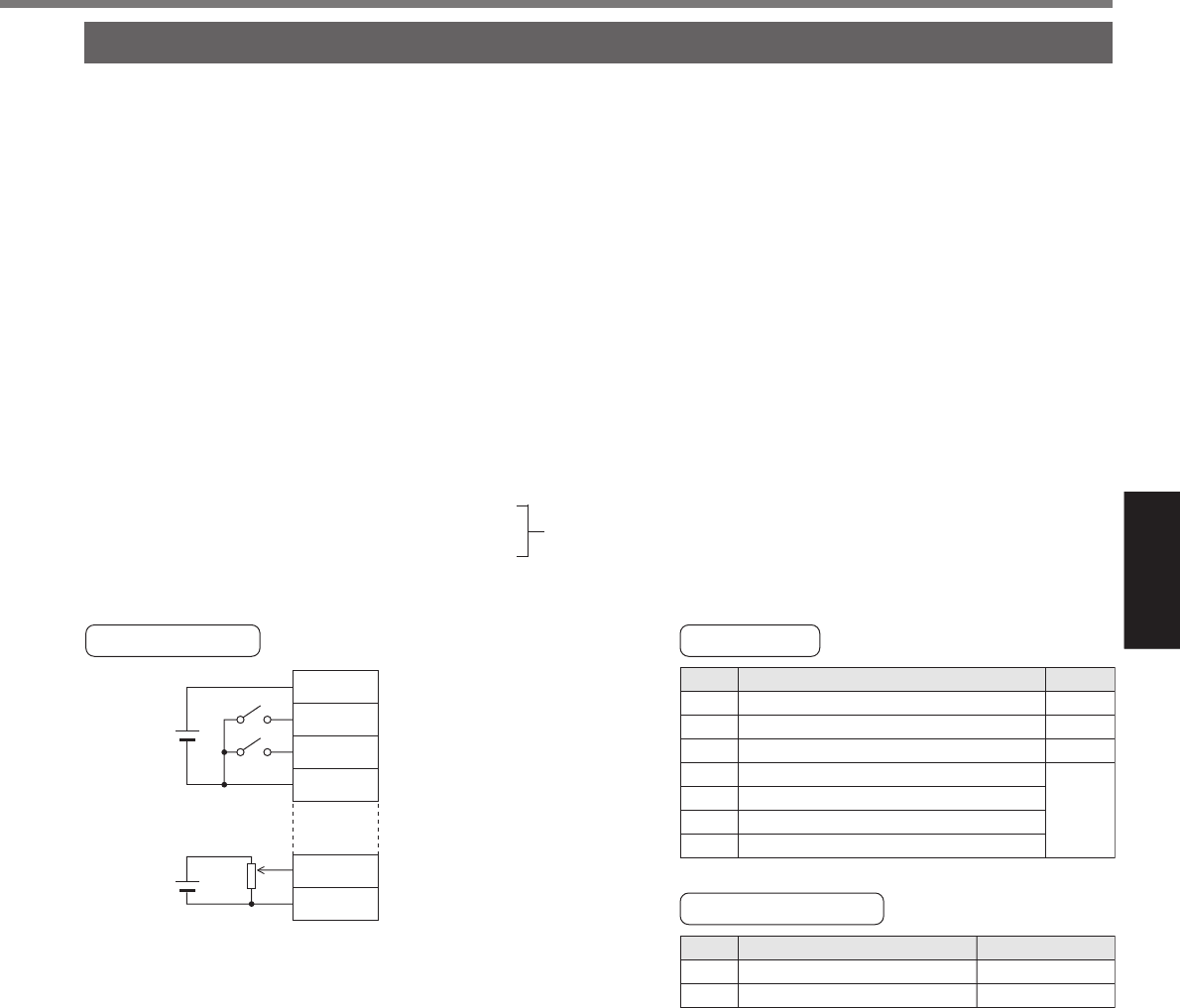
[Connection and setup of velocity control mode]
Connection and Setup of
Velocity Control Mode
Title
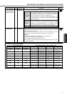
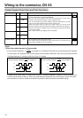
Setup of control mode
Invalidation of over-travel inhibit input
Selection of ZEROSPD input
Velocity command gain
Velocity command reversal
Velocity command offset
Setup of velocity command filter
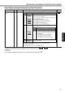
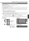
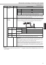
COM+
SRV-ON
SPR/TRQR
GND
ZEROSPD
COM–
7
29
14
15
26
41
DC
12V – 24V
Run with ZEROSPD
switch close, and
Stop with open
In case of one-directional
operation
In case of bi-directional
operation (CW/CCW),
provide a bipolar power
supply, or use with Pr06 = 3.
DC
10V
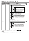
PrNo.
02
04
06
50
51
52
57
Setup value
1
1
1
Set up
as
required
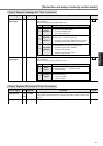
Title of signal
Servo-ON
Speed zero clamp
No.
0
5
Monitor display
+A
–
Parameter
Wiring Diagram
Input signal status
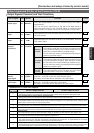
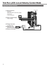
Trial Run by Connecting the Connector, CN X5
1) Connect the CN X5.
2) Enter the power (DC12-24V) to control signal (COM+, COM–)
3) Enter the power to the driver.
4) Confirm the default values of parameters.
5) Connect the Servo-ON input (SRV-ON, CN X5, Pin-29) and COM– (CN X5, Pin-14) to turn to Servo-ON
and energize the motor.
6) Close the speed zero clamp input (ZEROSPD) and apply DC voltage between velocity command input ,
SPR (CN X5, Pin-14) and GND (CN X5, Pin-15), and gradually increase from 0V to confirm the motor
runs.
7) Confirm the motor rotational speed in monitor mode.
• Whether the rotational speed is per the setup or not.
• Whether the motor stops with zero command or not.
8) If the motor does rotate at a micro speed with command voltage of 0, correct the command voltage
referring to P.74, "Automatic offset adjustment" of Preparation.
9) When you want to change the rotational speed and direction, set up the following parameters again.
Pr50 : Speed command input gain
Pr51 : Speed command input reversal
10)If the motor does not run correctly, refer to P.68, "Display of Factor for No-Motor Running" of Preparation.
Refer to P.152, "Parameter Setup"
(Parameters for Velocity/Torque Control)