


262
Troubleshooting
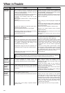
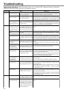
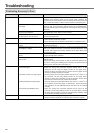
Positioning Accuracy Is Poor
Classification Causes Measures
Position command is not correct.
Captures the positioning complete signal
at the edge.
Shape or width of the command pulse is
not per the specifications.
Noise is superposed on deviation coun-
ter clear input CL (CN X5, Pin-5).
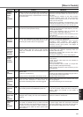
Position loop gain is small.
Setup of the positioning complete range
is large.
Command pulse frequency have excee-
ded 500kpps or 2Mpps.
Setup of the division/multiplication is not
correct.
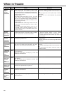
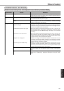
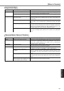
Velocity loop gain is proportion action at
motor in stall.
Each input signal of CN X5 is chattering.
1) Servo-ON signal
2) Deviation counter clear input signal
3) CW/CCW torque limit input signal
4) Command pulse inhibition input
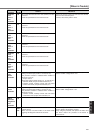
Load inertia is large.
Count the feedback pulses with a monitor function of the PANATERM
®
or
feedback pulse monitor mode of the console while repeating the
movement of the same distance. If the value does not return to the same
value, review the controller. Make a noise measure to command pulse.
Monitor the deviation at positioning complete signal reception with a
check pin (IM) or the waveform graphic function of the PANATERM
®
.
Make the controller capture the signal not at the edge but with some time
allowance.
If the shape of the command pulse is broken or narrowed, review the
pulse generating circuit. Make a noise measure.
Make a noise measure to external DC power supply and make no wiring
of the unused signal lines.
Check the position deviation with the monitor function of the PANATERM
®
or at the monitor mode of the console.
Increase the setup of Pr10 within the range where no oscillation occurs.
Lower the setup of Pr60 within the range where no chattering of
complete signal occurs.
Lower the command pulse frequency. Change the division/multiplication
ratio of 1st and 2nd numerator of command division/multiplication, Pr48
and Pr4B. Use a pulse line interface exclusive to line driver when pulse
line interface is used.
Check if the repetition accuracy is same or not. If it does not change, use
a larger capacity motor and driver.
• Set up Pr12 and Pr1A of time constant of velocity loop integration to
999 or smaller.
• Review the wiring and connection so that the connection between Pin-
27 and 41 of the gain switching input connector, CN X5 becomes off
while you set up Pr30 of 2nd gain setup, to 1.
1)Check the wiring and connection between Pin29 and 41 of the
connector, CN X5 using the display function of I/O signal status.
Correct the wiring and connection so that the servo-On signal can be
turned on normally. Review the controller.
2)Check the wiring and connection between Pin-30 and 41, 16 and 17 of
the connector, CN X5 using display function of I/O signal status.
Correct the wiring and connection so that the deviation counter clear
input can be turned on normally. Review the controller.
3 Check the wiring and connection between Pin-18 and 17, 16 and 17 of
the connector, CN X5 using tester or oscilloscope. Correct the wiring
and connection so that CW/CCW torque limit input can be entered
normally.
4)Check the wiring and connection between Pin-33 and 41of the
connector, CN X5 using display function of I/O signal status. Correct
the wiring and connection so that the command pulse inhibition input
can be entered normally. Review the controller.
Check the overshoot at stopping with graphic function of the PANATERM
®
.
If no improvement is obtained, increase the driver and motor capacity.
System
Adjustment
Parameter
Wiring
Installation