


359
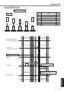
[Supplement]
Supplement
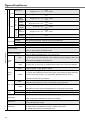
Function
Position control
Velocity controlTorque controlFull-closed controlCommon
Control input
Control input
Control output
Control input
Control output
Control input
Masking of unnecessary input
Division of encoder feedback pulse
Protective
function
Traceability of alarm data
Damping control function
Setup range of division/multiplication of
external scale
Control output
Speed control range
Internal velocity command
Soft-start/down function
Zero-speed clam
Control input
Control output
Speed limit function
Analog
input
Analog
input
Max. command pulse frequency
Input pulse signal format
Type of input pulse
Electronic gear (Division/
Multiplication of command pulse)
Electronic gear (Division/
Multiplication of command pulse)
Smoothing filter
Velocity command input
Torque limit command input
Velocity command input
Max. command pulse frequency
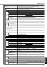
Real-time
Normal mode
Manual
Setup support software
Fit-gain function
Soft error
Hard error
Input pulse signal format
Smoothing filter
Torque limit command input
Speed limit input
Torque limit command input
Pulse
input
Pulse
input
Auto-gain
tuning
Setup
Analog
input
Analog
input
as a position command input
x
(1 to 10000) x 2
(0 to 17)
Process the command
pulse frequency
1 to 10000
as a position command input
x
(1 to 10000) x 2
(0 to 17)
Process the command
pulse frequency
1 to 10000
Inputs of 1) Servo-ON, 2) Alarm clear, 3) Gain switching, 4) Control mode switching,
5) CW over-travel inhibition and 7) CCW over-travel inhibition are common,
and other inputs vary depending on the control mode.
(1) Deviation counter clear, (2) Command pulse inhibition, (3) Damping control switching,
(4) Gain switching or Torque limit switching
Positioning complete (In-position)
Exclusive interface for line driver : 2Mpps, Line driver : 500kpps, Open collector : 200kpps
Support (1) RS422 line drive signal and (2) Open collector signal from controller.
(1) CW/CCW pulse, (2) Pulse signal/rotational direction signal, (3) 90˚C phase difference signal
Primary delay filter is adaptable to the command input
Selectable of (1) Position control for high stiffness machine and
(2) FIR type filter for position control for low stiffness machine.
Individual torque limit for both CW and CCW direction is enabled. (3V/rated torque)
(1) Speed zero clamp, (2) Selection of internal velocity setup,
(3) Gain switching or Torque limit switching input
(1) Speed arrival (at-speed)
Setup of scale and rotational direction of the motor against the command voltage is enabled with
parameter, with the permissible max. voltage input = Å} 10V and 6V/rated speed (default setup).
Individual torque limit for both CW and CCW direction is enabled. (3V/rated torque)
1 : 5000
8-speed with parameter setup
Individual setup of acceleration and deceleration is enabled, with 0 to 10s/1000r/min. Sigmoid
acceleration/deceleration is also enabled.
0-clamp of internal velocity command with speed zero clamp input is enabled.
(1) CW over-travel inhibition, (2) CCW over-travel inhibition, (3) Speed zero clamp
(1) Speed arrival (at-speed)
Setup of scale and CW/CCW torque generating direction of the motor against the command
voltage is enabled with parameter, with the permissible max. voltage input = Å} 10V and
3V/rated speed (default setup).
Speed limit input by analog voltage is enabled. Scale setup with parameter.
Speed limit value with parameter or analog input is enabled.
(1) CW over-travel inhibition, (2) CCW over-travel inhibition (3) Deviation counter clear, (4)
Command pulse input inhibition, (5) Electronic gear switching, (6) Damping control switching
(1) Full-closed positioning complete (in-position)
500kpps (photo-coupler input), 2Mpps (Exclusive input for line driver)
Differential input. Selectable with parameter ((1) CCW/CW, (2) A and B-phase, (3) Command
and direction
Primary delay filter is adaptable to the command input.
Individual torque limit for both CW and CCW direction is enabled. (3V/rated torque)
Setting of ratio between encoder pulse (denominator) and external scale pulse (numerator) is
enabled within a range of (1 to 10000) x 2
(0 – 17)
/ (1 to 10000).
Corresponds to load inertia fluctuation, possible to automatically set up parameters related to
notch filter.
Estimates load inertia and sets up an appropriate servo gain.
Automatically searches and sets up the value which makes the fastest settling time with
external command input.
Masking of the following input signal is enabled.
(1) Over-travel inhibition, (2) Torque limit, (3) Command pulse inhibition, (4) Speed-zero clamp
Set up of any value is enabled (encoder pulses count is the max.).
Over-voltage, under-voltage, over-speed over-load, over-heat, over-current and encoder error etc.
Excess position deviation, command pulse division error, EEPROM error etc.
Traceable up to past 14 alarms including the present one.
Manual setup with parameter
5push switches on front panel
PANATERM
®
(Supporting OS : Windows95, Windows98, Windows ME, Windows2000,
Windows.NET and Windows XP)
MODE SET