


131
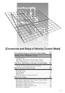
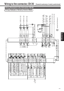
[Connection and setup of velocity control mode]
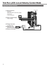
Connection and Setup of
Velocity Control Mode
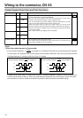
Connector Pin No. of X5 Pr05, Internal/external switching of speed setup
3
1st speed of speed
setup (Pr53)
2nd speed of speed
setup (Pr54)
3rd speed of speed
setup (Pr55)
4th speed of speed
setup (Pr56)
5th speed of speed
setup (Pr74)
6th speed of speed
setup (P75)
7th speed of speed
setup (Pr76)
8th speed of speed
setup (Pr77)
2
1st speed of speed
setup (Pr53)
2nd speed of speed
setup (Pr54)
3rd speed of speed
setup (Pr55)
Analog speed command
(CN X5, Pin-14)
1st speed of speed
setup (Pr53)
2nd speed of speed
setup (Pr54)
3rd speed of speed
setup (Pr55)
Analog speed command
(CN X5, Pin-14)
1
1st speed of speed
setup (Pr53)
2nd speed of speed
setup (Pr54)
3rd speed of speed
setup (Pr55)
4th speed of speed
setup (Pr56)
1st speed of speed
setup (Pr53)
2nd speed of speed
setup (Pr54)
3rd speed of speed
setup (Pr55)
4th speed of speed
setup (Pr56)
0
Analog speed command
(CN X5, Pin-14)
Analog speed command
(CN X5, Pin-14)
Analog speed command
(CN X5, Pin-14)
Analog speed command
(CN X5, Pin-14)
Analog speed command
(CN X5, Pin-14)
Analog speed command
(CN X5, Pin-14)
Analog speed command
(CN X5, Pin-14)
Analog speed command
(CN X5, Pin-14)
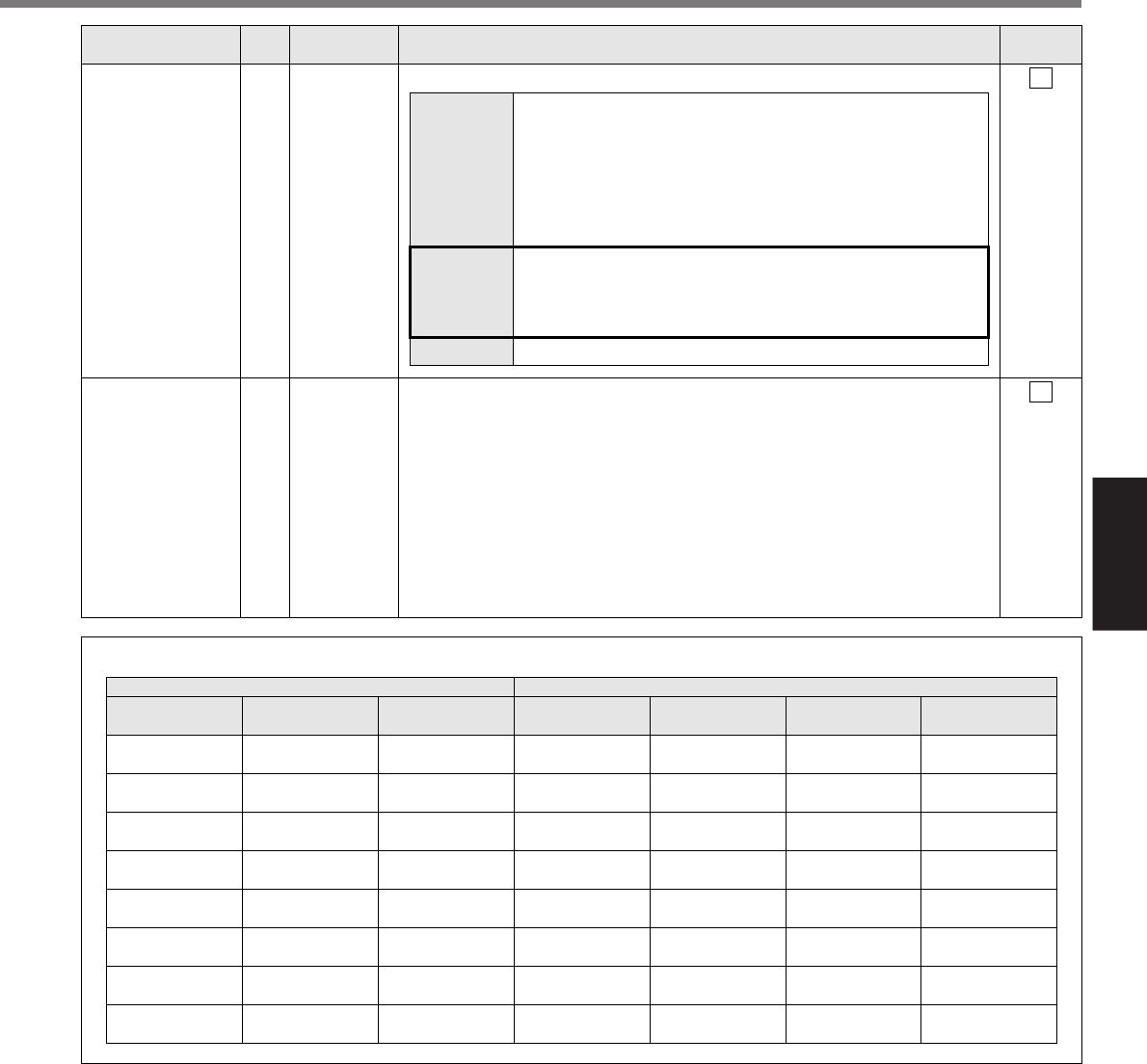
Pin-28
INTSPD3(DIV)
open
open
open
open
short
short
short
short
Pin-30
INTSPD2(CL)
open
open
short
short
open
open
short
short
Pin-33
INTSPD1(INH)
open
short
open
short
open
short
open
short
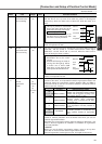
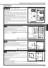
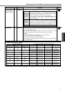
• Selection of Internal Speed
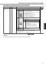
• You can switch the numerator of electronic gear.
• By connecting to COM–, you can switch the numerator of
electronic gear from Pr48 (1st numerator of electronic
gear) to Pr49 (2nd numerator of electronic gear)
• For the selection of command division/multiplication, refer
to the table of next page, "Numerator selection of
command scaling"
• Input of internal speed selection 3 (INTSPD3).
•
You can make up to 8-speed setups combining INH/
INTSPD1 and CL/INTSPD2 inputs. For details of setup,
refer to the table of P.131, "Selection of Internal Speed".
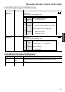
• This input is invalid.
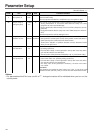
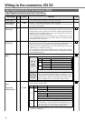
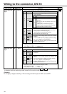
Position/
Full-closed
control
Velocity
control
Torque control
Title of signal
Pin No.
Symbol Function
I/F circuit
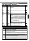
Servo-ON input
29
SI
P.128
SRV-ON
• Turns to Servo-ON status by connecting this input to COM–.
• Turns to Servo-OFF status by opening connection to COM–, and current
to the motor will be shut off.
• You can select the dynamic brake action and the deviation counter
clearing action at Servo-OFF with Pr69 (Sequence at Servo-OFF).
<Caution>
1.Servo-ON input becomes valid approx. 2 sec after power-on.
(see P.42, "Timing Chart" of Preparation.)
2.Never run/stop the motor with Servo-ON/OFF.
3.After shifting to Servo-ON, allow 100ms or longer pause before entering
the pulse command.
Internal
command speed
selection 3 input
28
SI
P.128
INTSPD3
• Function varies depending on the control mode.