


274
Absolute System
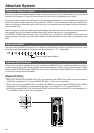
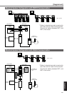
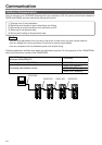
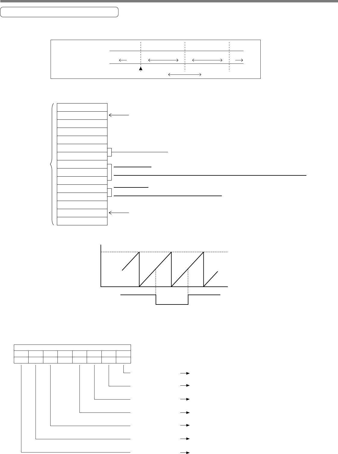
Composition of Absolute Data
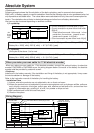
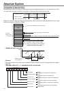
Absolute data consists of singe-turn data which shows the absolute position per one revolution and multi-
turn data which counts the number of revolution of the motor after clearing the encoder.
Single-turn data and multi-turn data are composed by using 15-character data (hexadecimal binary code)
which are received via RS232 or RS485.
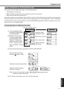
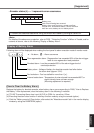
<Remark>
If the multi-turn data of the above fig. is between 32768 and 65535, convert it to signed date after deduct-
ing 65536.
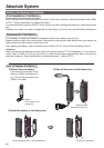
• Encoder status (L)-----1 represents error occurrence.
• Details of multi-turn data
0Bh
RSW (ID)
D2h
03h
11h
Encoder status (L)
Setup value of RSW (ID) of the front panel
Encoder status (H)
Single-turn data (L)
Single-turn data (M)
Single-turn data (H)
Multi-turn data (L)
Multi-turn data (H)
00h
Error code
Checksum
Becomes to 0 when the communication is
carried out normally. If not 0, capture the
absolute data from the driver again
Single-turn data
=Single-turn data (H) x 10000h + Single-turn data (M) x 100h + Single-turn data (L)
Multi-turn data
=Multi-turn data (H) x 100h + Multi-turn data (L)
Date : 0 to 65535, Range : -32767 to 32767
Refer to next page, "Encoder status".
Received
absolute data
(15 characters)
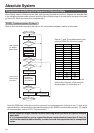
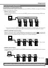
Single-turn data
CW
origin
CCW
–1 0 0 1 1 2
131071 0,1,2 … …13107 1 0,1,2 131071 0,1,
Multi-turn data
Motor rotational direction
65535
CW 0 CCW
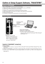
Error
Absolute counter over
error protection
Normal Error
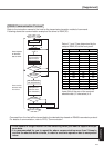
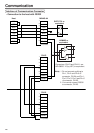
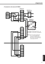
Multi-turn data
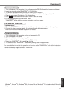
Encoder status (L)
bit7
bit6 bit5 bit4 bit3 bit2 bit1
Over-speed
Err42
(Absolute over-speed error protection)
bit0
0
Multi-turn error
Battery error
Battery alarm
Full absolute status
Err47
(Absolute status error protection)
Err44
(Absolute single-turn counter error protection)
Err41
(Absolute counter over error protection)
Counter error
Counter overflow
Err45
(Absolute multi-turn counter error protection)
Err40
(Absolute system down error protection)
Battery alarm