


41
[Preparation]
Preparation
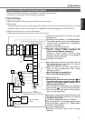
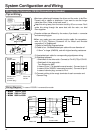
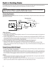
Wiring to the Connector, CN X5 (Connection to Host Controller)
• Tips on wiring
Controller
3m
or shorter
30cm or longer
COM+
GND
1
CN X5
COM–
FG
V
DC
Power
supply
Motor
2
Peripheral apparatus such as host controller should be located
within3m.
Separate the main circuit at least 30cm away.
Don't pass them in the same duct, nor bind them together.
Power supply for control signals (V
CC) between COM+ and COM– (VDC)
should be prepared by customer.
Use shield twisted pair for the wiring of command pulse input and
encoder signal output.
Don't apply more than 24V to the control signal output terminals, nor run
50mA or more to them.
When the relay is directly driven by the control output signals, install a
diode in parallel with a relay, and in the direction as the Fig. shows. The
driver might be damaged without a diode installment, or by reverse
direction.
Frame ground (FG) is connected to the earth terminal inside of the
driver.
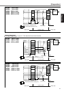
•
For detailed information, refer to Wiring Diagram at each control mode, P.83 (Position control mode),
P.127 (Velocity control mode), P.161 (Torque control mode) and P.192 (Full-closed control mode).
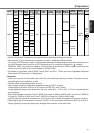
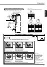
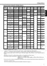
• Specifications of the Connector, CN X5
<Note>
For details, refer to P.312, "Options" of Supplement.
<Remarks>
• Tightening torque of the screws for connector (CN X5) for the connection to the host to be 0.3 to 0.35N
•
m.
Larger tightening torque than these may damage the connector at the driver side.
Connector at driver side
52986-5071
Part name
Connecter (soldering type)
Connector cover
Connecter (soldering type)
Connector cover
Part No.
54306-5011 or
54306-5019 (lead-free)
54331-0501
10150-3000VE
10350-52A0-008
Connecter to be prepared by customer
Manufacturer
Molex Inc.
Sumitomo 3M
or