82
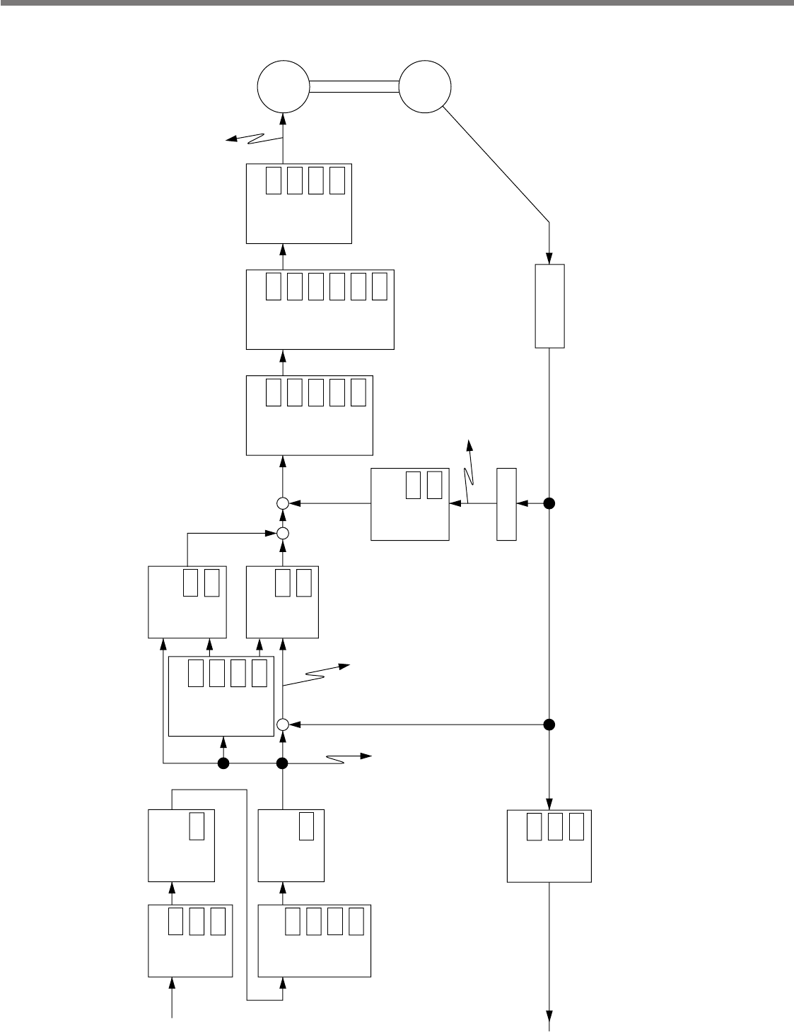
Control Block Diagram of Position Control Mode
PULS
SIGN
Input setup
Pulse
train
Positional deviation
monitor
Actual speed monitor
Command speed
monitor
Feedback pulses
Serial communication
data
OA/OB/OZ
Pr40
Input
selection
Pr41
Reversal
Pr42Mode
Division/
Multiplication
Pr48
1st
numerator
Pr49
2nd
numerator
Pr4A
Multiplier
Pr4B
Denominator
Damping control
Pr2B
1st
frequency
Pr2C1st filter
Pr2D
2nd
frequency
Pr2E2nd filter
Velocity control
Pr11
1st
proportion
Pr12
1st
integration
Pr19
2nd
proportion
Pr1A
2nd
integration
Pr20
Inertia ratio
Notch filter
Pr1D
1st
frequency
Pr1E1st width
Pr28
2nd
frequency
Pr292nd width
Pr2A2nd depth
Pr2F
Adaptation
Torque filter
Motor
Torque command monitor
Pr14
1st time
constant
Pr1C
2nd time
constant
Pr5E1st limit
Pr5F
2nd limit
Pr4D
Average
travel times
Primary delay
smoothing
Pr4C
Selection
Division
Pr44
Numerator
Pr45
Denominator
Pr46
Selection
Velocity feed
forward
Pr15Gain
Pr16Filter
Speed detection
filter
Pr131st
Pr1B2nd
Speed detection
Encoder reception
processing
Position control
Pr101st
+
++
–
+
–
Pr182nd
Encoder
FIR smoothing


