


99
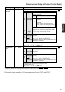
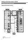
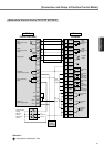
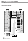
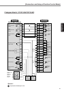
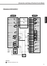
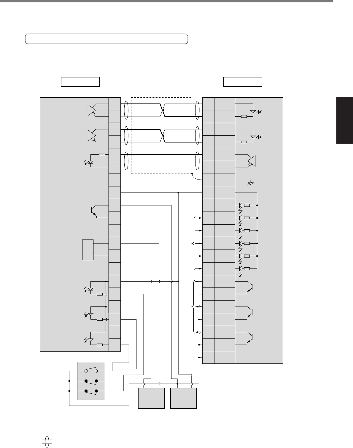
[Connection and Setup of Position Control Mode]
Connection and Setup of
Position Control Mode
Yokogawa Electric , F3YP14-0N/F3YP18-0N
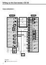
240Ω
CW
pulse
command
input
14a
13a
12a
11a
15a
16a
10a
9a
8b
8a
1a
3a
2b
4a
PULS1
PULS2
SIGN1
SIGN2
OZ+
OZ–
GND
COM+
CL
SRV-ON
GAIN/TC
A-CLR
CCWL
CWL
S-RDY
+
S-RDY
–
ALM+
ALM–
COIN+
COIN–
COM–
3
4
5
6
23
24
13
7
30
29
27
31
9
8
35
34
37
36
39
38
41
CCW
pulse
command
input
Counter clear
input
Servo-ON
input
Servo-Ready
output
Servo-Alarm
output
Positioning
complete
output
Alarm clear
input
CW
over-travel
inhibit input
CCW
over-travel
inhibit input
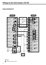
PLC
F3YP14-0N/F3YP18-0N
Driver
A4-series
Z-phase
output
from
PLC I/O
outpu
t
to
PLC I/O
input
V+
GND
CW
pulse command
output
CCW
pulse command
output
Origin line driver
input
Deviation pulse clear
signal output
Origin proximity
input
CCW limit input
CW limit input
5V power supply
for pulse output
220Ω
220Ω
4.7
k
Ω
4.7
k
Ω
4.7
k
Ω
4.7
k
Ω
4.7
k
Ω
4.7
k
Ω
7.4kΩ
7.4kΩ
7.4kΩ
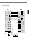
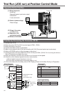
Gain switching/
Torque limit
switching input
Origin proximity
sensor
CW limit
sensor
CCW limit
sensor
GND + 5V
DC5V
Power supply
GND + 24V
DC24V
Power supply
represents twisted pair wire.
<Remark>