


263
[When in Trouble]
When in Trouble
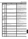
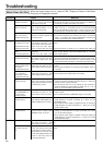
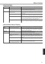
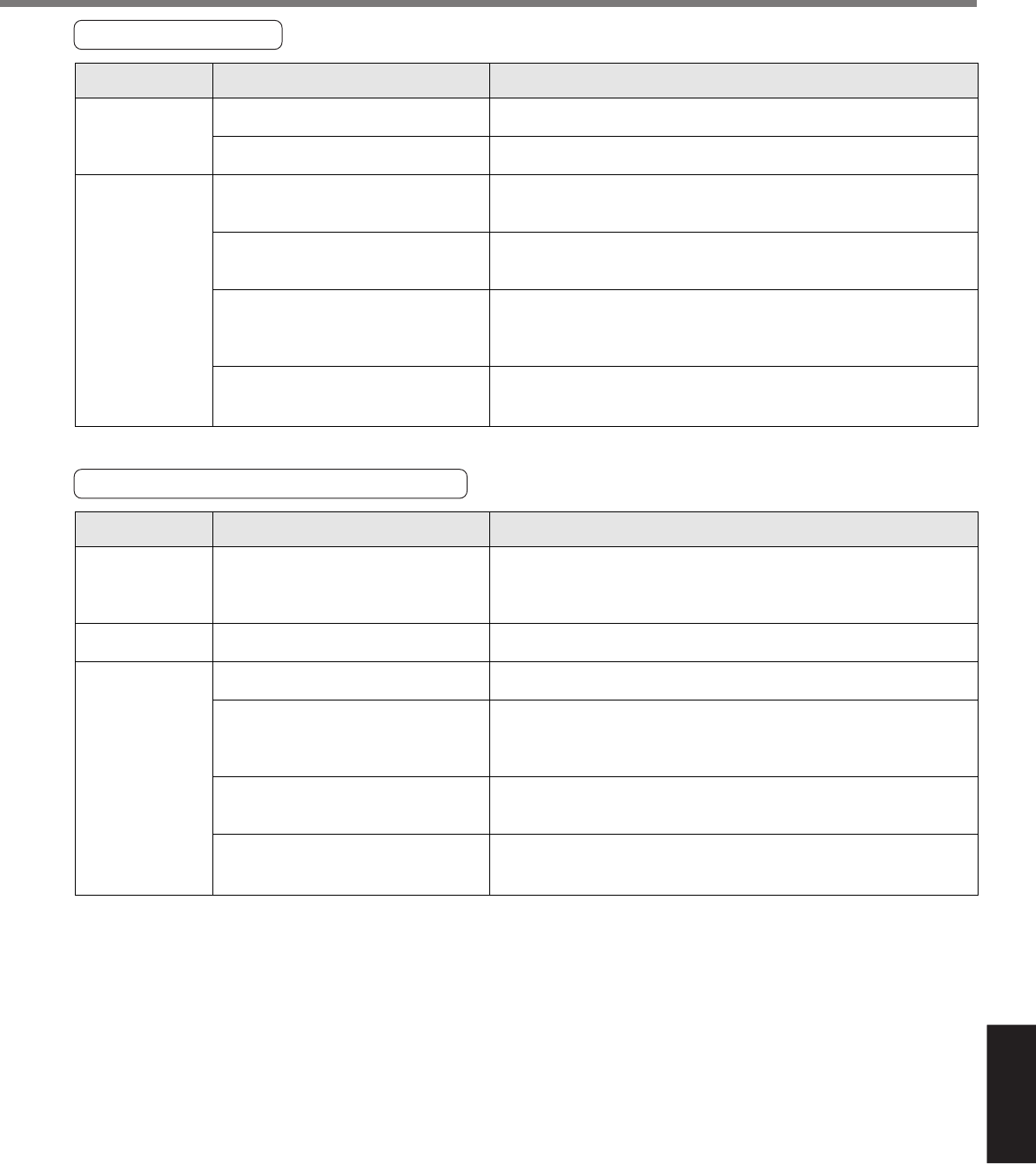
Abnormal Motor Noise or Vibration
Classification Causes Measures
Noise is on the speed command.
Gain setup is large.
Velocity detection filter is changed.
Resonance of the machine and
the motor.
Motor bearing
Electro-magnetic sound, gear noise,
rubbing noise at brake engagement, hub
noise or rubbing noise of encoder
Measure the speed command inputs of Pin-14 and 15 of the connector,
CN X5 with an oscilloscope. Reduce noise (installation of noise filter or
ferrite core), shield treatment of I/F cables, use of a twisted pair,
separation of power and signal lines.
Lower the gain by setting up lower values to Pr11 and 19, of velocity
loop gain and Pr10 and 18 of position loop gain.
Enlarge the setup of Pr13 and 1B, velocity detection filter within the
range where noise level is acceptable, or return to default value.
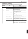
Re-adjust Pr14 and 1C (Torque filter). Check if the machine resonance
exists or not with frequency characteristics analyzing function of the
PANATERM
®
. Set up the notch frequency to Pr1D or Pr28 if resonance
exists.
Check the noise and vibration near the bearing of the motor while
running the motor with no load. Replace the motor to check. Request for
repair.
Check the noise of the motor while running the motor with no load.
Replace the motor to check. Request for repair.
Wiring
Adjustment
Installation
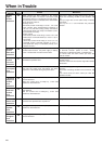
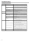
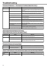
Origin Point Slips
Classification Causes Measures
Z-phase is not detected.
Homing creep speed is fast
Chattering of proximity sensor (proximity
dog sensor) output
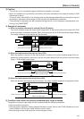
Noise is on the encoder line.
No Z-phase signal output
Miswiring of Z-phase output
Check that the Z-phase matches to the center of proximity dog. Execute
the homing matching to the controller correctly.
Lower the homing speed at origin proximity. Or widen the origin sensor.
Check the dog sensor input signal of the controller with oscilloscope.
Review the wiring near to proximity dog and make a noise measure or
reduce noise.
Reduce noise (installation of noise filter or ferrite core), shield treatment
of I/F cables, use of a twisted pair or separation of power and signal
lines.
Check the Z-phase signal with oscilloscope. Check that the Pin-13 of the
connector, CN X5 is connected to the earth of the controller. Connect the
earth of the controller because the open collector interface is not
insulated. Replace the motor and driver. Request for repair.
Check the wiring to see only one side of the line driver is connected or
not. Use a CZ output (open collector if the controller is not differential
input.
System
Wiring