


64
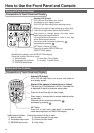
How to Use the Front Panel and Console
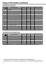
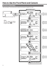
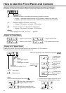
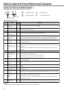
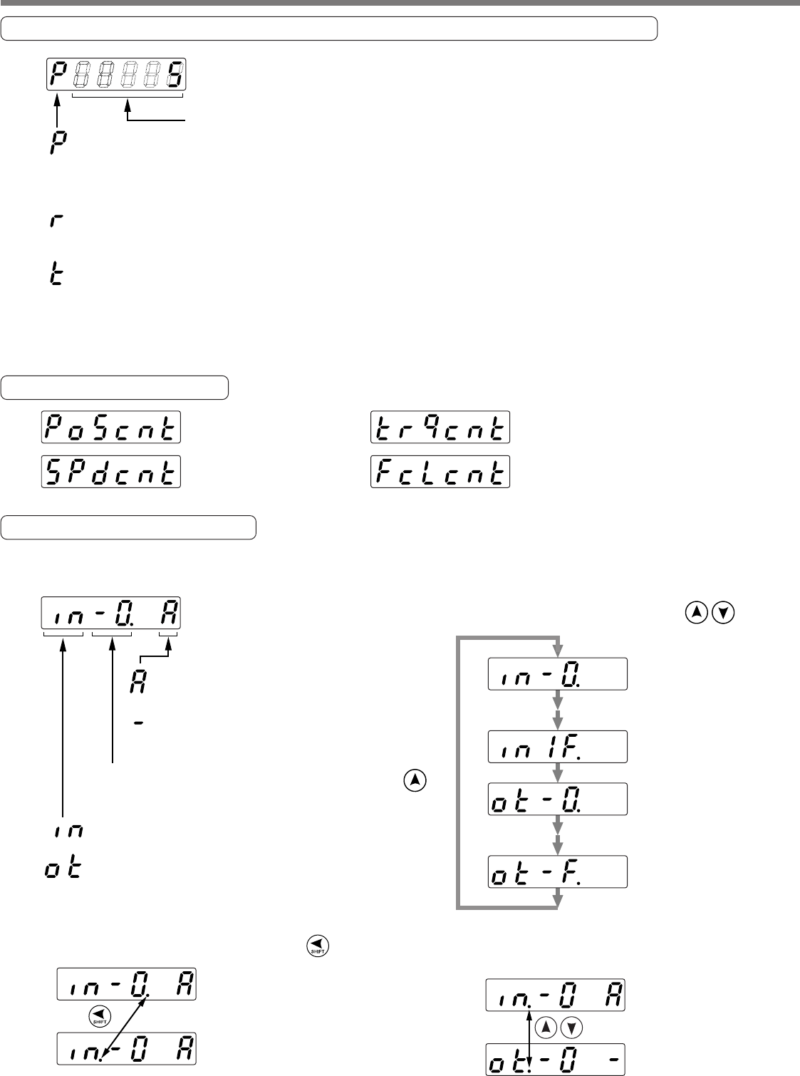
Display of Position Deviation, Motor Rotational Speed and Torque Output
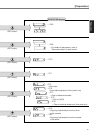
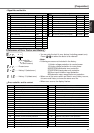
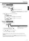
Display of Control Mode
..........Positional deviation (cumulative pulse counts of deviation counter)
• – display : generates rotational torque of CW direction (viewed from shaft end)
no display : generates rotational torque of CCW direction (viewed from shaft end)
..........Rotational speed of the motor unit [r/min]
• – display : CW rotation, no display : CCW rotation
..........Torque command unit [%] (100 for rated torque)
• – display : CW rotation, no display : CCW rotation
Data
<Note>
“
+
”
is not displayed on LED, but only
“
-
”
appears.
.....Position control mode
.....Velocity control mode
.....Torque control mode
.....Full-closed control mode
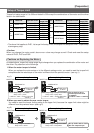
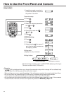
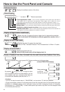
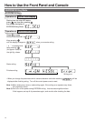
Display of I/O Signal Status
Displays the control input and output signal to be connected to CN X5 connector.
Use this function to check if the wiring is correct or not.
.....Input signal
.....Output signal
(Lowest place
No. of input
signal)
(Highest place
No. of input
signal)
(Lowest place
No. of output
signal)
(Highest place
No. of output
signal)
Signal No.
(Hexadecimal number, 0-1F)
.....Active
(This signal is valid)
.....Inactive
(This signal is invalid)
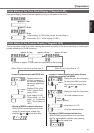
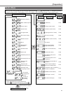
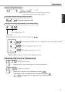
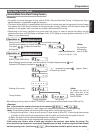
Select the signal No. to be monitored by pressing .
Transition when
pressing .
<Note>
• Shift the flashing decimal point with .
• The other way to change signal No. at I/O
selection modeSignal selection mode.
(Right side of decimal point :
Signal selection mode)
(Left side of decimal point :
Input/Output selection mode)