


89
[Connection and Setup of Position Control Mode]
Connection and Setup of
Position Control Mode
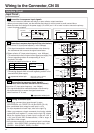
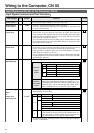
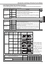
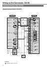
Title of signal
Pin No.
Symbol Function
I/F circuit
PI2
P.84
Command pulse
input 1
Command pulse
sign input 1
44
45
46
47
PULSH1
PULSH2
SIGNH1
SIGNH2
• Input terminal for position command pulse. You can select by setting up
Pr40 (Selection of command pulse input) to 1.
• This input becomes invalid at such control mode as velocity control or
torque control, where no position command is required.
• Permissible max. input frequency is 2Mpps.
• You can select up to 6 command pulse input formats with Pr41 (Setup of
command pulse rotational direction) and Pr42 (Setup of command pulse
input mode).
For details, refer to the table below, "Command pulse input format".
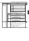
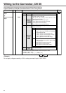
Title of signal
Pin No.
Symbol Function
I/F circuit
PI1
P.84
Command pulse
input 2
Command pulse
sign input 2
1
3
4
2
5
6
OPC1
PULS1
PULS2
OPC2
SIGN1
SIGN2
• Input terminal for the position command. You can select by setting up Pr40
(Selection of command pulse input) to 0.
• This input becomes invalid at such control mode as the velocity control or
torque control, where no position command is required.
• Permissible max. input frequency is 500kpps at line driver input and
200kpps at open collector input.
• You can select up to 6 command pulse input formats with Pr41 (Setup of
command pulse rotational direction) and Pr42 (Setup of command pulse
input mode).
For details, refer to the table below, "Command pulse input format".
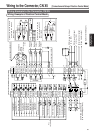
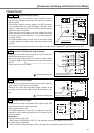
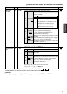
• Pulse train interface
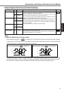
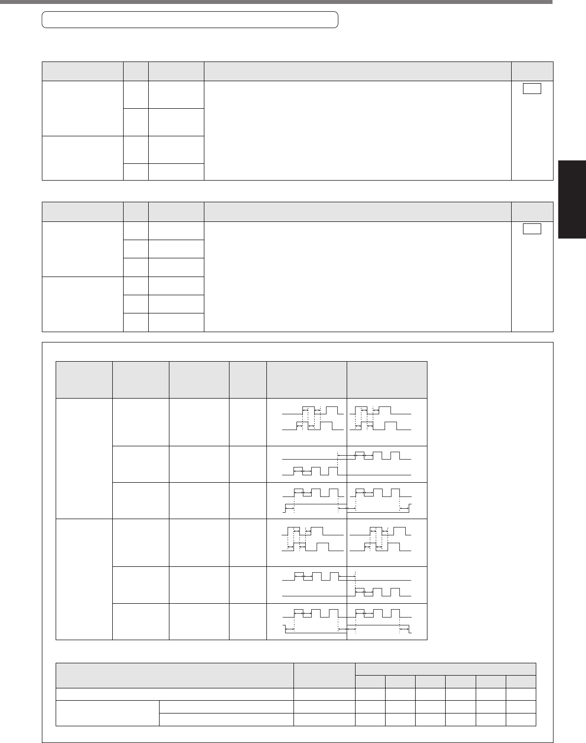
Input Signals (Pulse Train) and Their Functions
You can select appropriate interface out of two kinds, depending on the command pulse specifications.
• Pulse train interface exclusive for line driver
Pr41 Setup value
(Setup of
command pulse
rotational direction)
Pr42
Setup value
(Setup of
command pulse
input mode)
Signal
title
CCW command
B-phase advances to A by 90
°
.
B-phase delays from A by 90
°
.
CW command
Command
pulse
format
t1
A-phase
B-phase
t1 t1 t1
t1 t1t1 t1
t2 t2
t2
t3
t2
t4
“H”
“L”
t5t4
t6 t6
t6 t6
t5
B-phase advances to A by 90
°
.
B-phase delays from A by 90
°
.
t1
A-phase
B-phase
t1t1 t1
t1 t1 t1 t1
t2 t2
t2
t3
t2
t4
“L”
“H”
t5t4
t6 t6 t6 t6
t5
0 or 2
0 or 2
01
3
11
3
PULS
SIGN
PULS
SIGN
PULS
SIGN
PULS
SIGN
PULS
SIGN
PULS
SIGN
2-phase pulse
with 90°
difference
(A+B-phase)
CW pulse train
+
CCW pulse train
Pulse train
+
Sign
2-phase pulse
with 90°
difference
(A+B-phase)
CW pulse train
+
CCW pulse train
Pulse train
+
Sign
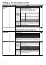
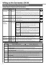
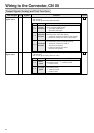
• Command pulse input format
Line driver interface
Open collector interface
Pulse train interface exclusive for line driver
Pulse train interface
Input I/F of PULS/SIGN signal
Permissible max.
input frequency
2Mpps
500kpps
200kpps
t
1
500ns
2µs
5µs
Minimum necessary time width
t
2
250ns
1µs
2.5µs
t
3
250ns
1µs
2.5µs
t
4
250ns
1µs
2.5µs
t
5
250ns
1µs
2.5µs
t
6
250ns
1µs
2.5µs
• Permissible max. input frequency of command pulse input signal and min. necessary time width
Set up the rising/falling time of command pulse input signal to 0.1µs or shorter.
• PULS and SIGN repre-
sents the outputs of pulse
train in put circuit. Refer
to the fig. of P.84, "Input
Circuit".
• In case of CW pulse train
+ CCW pulse train and
pulse train + sign, pulse
train will be cap tured at
the rising edge.
• In case of 2-phase pulse,
pulse train will be cap-
tured at each edge.