


317
[Supplement]
Supplement
1
2
3
4
5
6
7
8
9
10
Pin
No.
color
11
12
13
14
15
16
17
18
19
20
Orange (Black2)
Yellow (Black1)
Gray (Red2)
Gray (Black2)
White (Red2)
Yellow (Red2)
Pink (Red2)
White (Black2)
Orange (Red1)
Orange (Black1)
Gray (Red1)
Gray (Black1)
White (Red1)
White (Black1)
Yellow (Red1)
Pink (Red1)
Pink (Black1)
Orange (Red2)
Pin
No.
color
21
22
23
24
25
26
27
28
29
30
Orange (Red3)
Orange (Black3)
Gray (Red3)
Gray (Black3)
White (Red3)
White (Black3)
Yellow (Red3)
Yellow (Black3)
Pink (Red3)
Pink (Black3)
Pin
No.
color
31
32
33
34
35
36
37
38
39
40
Orange (Red4)
Orange (Black4)
Gray (Red4)
White (Red4)
White (Black4)
Yellow (Red4)
Yellow (Black4)
Pink (Red4)
Pink (Black4)
Gray (Black4)
Pin
No.
color
41
42
43
44
45
46
47
48
49
50
Orange (Red5)
Orange (Black5)
Gray (Red5)
White (Red5)
White (Black5)
Yellow (Red5)
Yellow (Black5)
Pink (Red5)
Pink (Black5)
Gray (Black5)
Pin
No.
color
Yel (Blk2)/
Pink (Blk2)
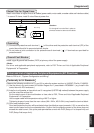
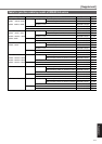
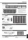
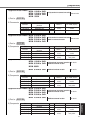
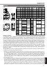
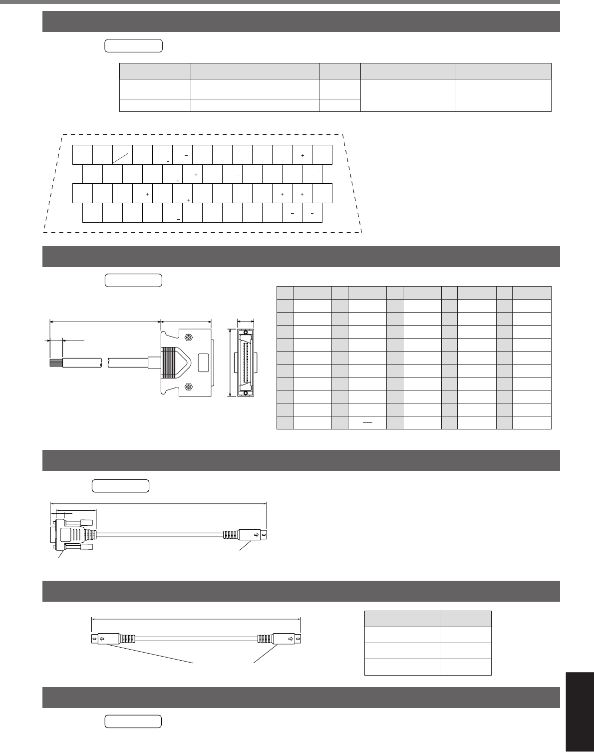
3) Pin disposition (50 pins) (viewed from the soldering side)
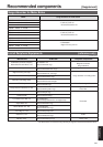
Connector
Connector cover
Title
54331-0501
QuantityPart No. Manufacturer Note
26
ZEROSPD/
VS-SEL
28
DIV/
INTSPD3
30
CL
INTSPD2
32
C-
MODE
34
S-
RDY
36
ALM
38
COIN
-
/
EX-COIN
-
/
AT-SPEED
-
40
TLC
42
IM
44
PULSH1
46
SIGNH1
48
OB
27
GAIN/
TL-SEL
29
SRV
-ON
31
A-
CLR
33
INH/
INTSPD1
35
S-
RDY
37
ALM
39
COIN
+
/
EX-COIN
+
/
AT-SPEED
+
41
COM
43
SP
45
PULSH2
47
SIGNH2
49
OB
1
OPC1
3
PULS1
5
SIGN1
7
COM
9
CCWL
11
BRK-
OFF
13
GND
15
GND
17
GND
19
CZ
21
OA
23
OZ
2
OPC2
4
PULS2
6
SIGN2
8
CWL
10
BRK-
OFF
12
ZSP
14
SPR/
TRQR/SPL
/TRQR
16
CCWTL
18
CWTL
20
NC
22
OA
24
OZ
50
FG
25
GND
<Cautions>
1) Check the stamped pin-No. on the
connector body while making a wiring.
2) For the function of each signal title or
its symbol, refer to the wiring example
of the connector CN I/F.
3) Check the stamped pin-No. on the
connector body while making a wiring.
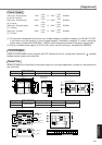
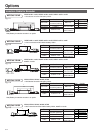
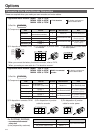
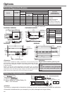
1) Par No. DV0P4360
2) Dimensions
3) Table for wiring
Cable of 2m is connected.
1
25
50
26
(52.35)
2000
+200
0
50
+10
0
(39)
12.7
<Remarks>
Color designation of the cable
e.g.) Pin-1 Cable color : Orange
(Red1) : One red dot on the cable
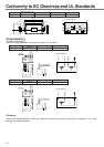
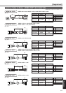
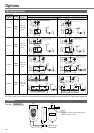
Par No. DV0P1960 (DOS/V machine)
L[mm]
DVOP1970
DVOP1971
DVOP1972
Part No.
200
500
1000
Mini-DIN 8P
MD connector
L
1) Part No. DV0P4460 (English/Japanese version)
2) Supply media : CD-ROM
<Caution>
For setup circumstance, refer to the Instruction Manual of
[PANATERM
®
].
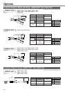
1
1
54306-5011 or
54306-5019
(lead-free)
For CN X5 (50-pins)
Molex Inc.
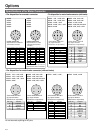
1) Par No. DV0P4350
2)
Components
D-sub connector 9P
Mini-DIN 8P
MD connector
2000
33
18
Connector Kit for External Peripheral Equipments
Interface Cable
Communication Cable (for connection to PC)
Communication Cable (for RS485)
Setup Support Software “PANATERM
®
”