


237
[Adjustment]
Adjustment
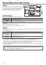
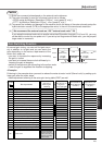
Auto-Gain Tuning Action
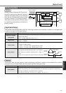
(1) In the normal mode auto-gain tuning, you can set up the response with machine stiffness No..
Machine stiffness No.
•
Represents the degree of machine stiffness of the customer's machine and have values from o to 15.
You can set a higher No. to the high stiffness machine and set up a higher gain.
• Usually start setting up with a lower value and increase gradually to repeat auto-gain tuning in the
range where no oscillation, no abnormal noise, nor vibration occurs.
(2) This tuning repeats max. 5 cycles of the action pattern set with Pr25 (Normal mode auto-gain tuning
action). Action acceleration will be doubled every one cycle after third cycle. Tuning may finish, or action
acceleration does not vary before 5th cycle depending on the load, however, this is nor an error.
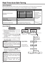
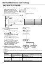
How to Operate
(1) Set up the action pattern with Pr25.
(2) Shift the load to the position where no hazard is expected even though the action pattern which is set
with Pr25 is executed.
(3) Prohibit the command entry.
(4) Turn to Servo-ON.
(5) Start up the auto-gain tuning.
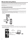
Use the front panel or the "PANATERM
®
".
For the operation of the front panel, refer to P.71, "Auto-Gain Tuning Mode" of Preparation.
(6) Adjust the machine stiffness to the level at which no vibration occurs and obtain the required response.
(7) Write the result to EEPROM, if it is satisfactory.
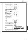
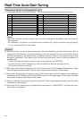
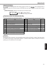
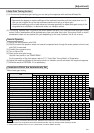
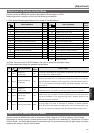
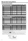
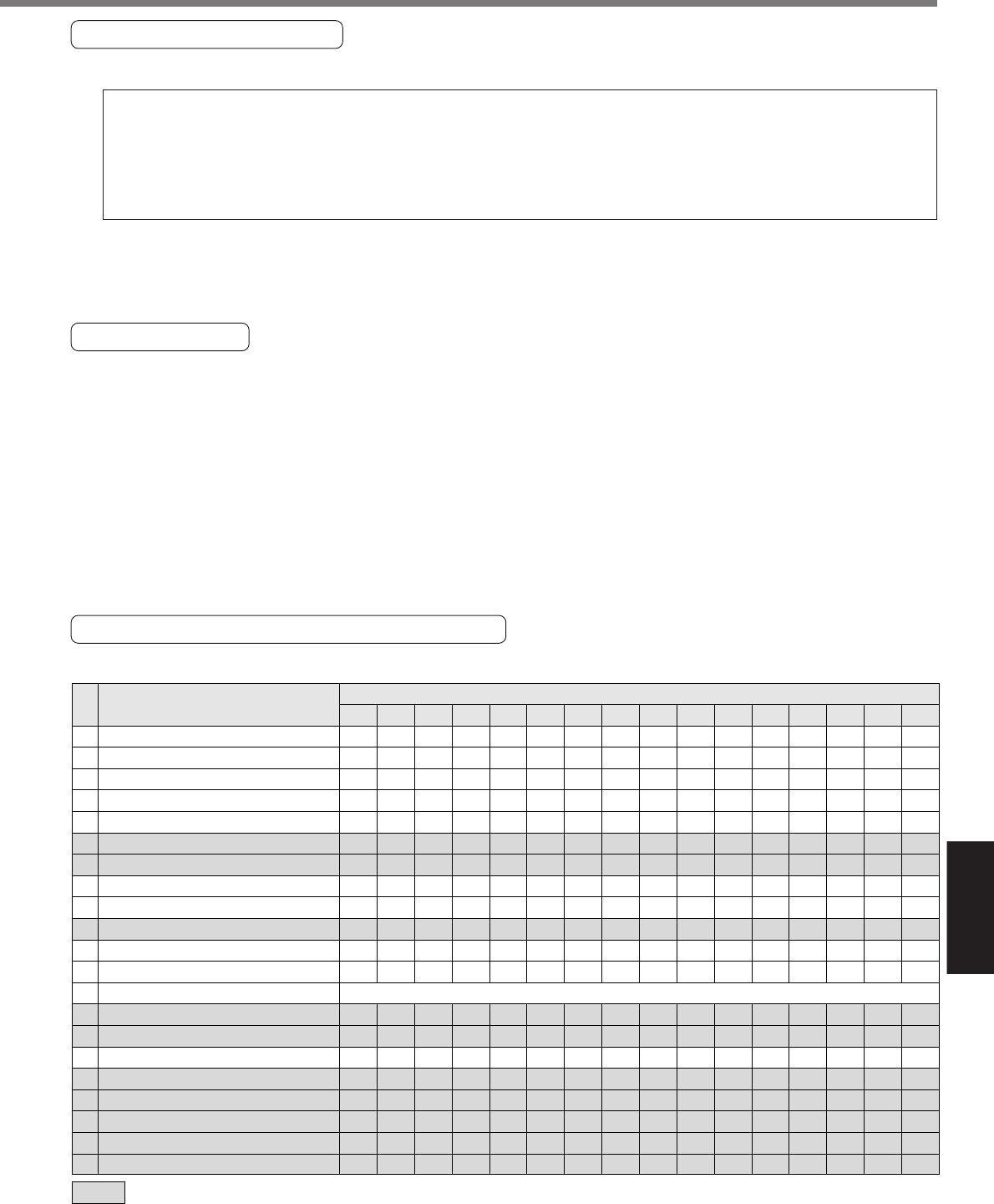
Parameters Which Are Automatically Set
Table of auto-gain tuning
10 1st gain of position loop
11 1st gain of velocity loop
12
1st time constant of velocity loop integration
13 1st filter of velocity detection
14
1st time constant of torque filter time *2
15 Velocity feed forward
16 Velocity FF filter
18 2nd gain of position loop
19 2nd gain of velocity loop
1A
2nd time constant of velocity loop integration
1B 2nd filter of speed detection
1C
2nd time constant of torque filter
*
2
20 Inertia ratio
27
Setup of instantaneous velocity observer
30 2nd gain setup
31 1st mode of control switching
*
1
32 1st delay time of control switching
33 1st level of control switching
34 1st Hysteresis of control switching
35 Switching time of position gain
36 2nd mode of control switching
0
[1]
2
3 [4]
5
6
7
8
9
10 11 12 13
14
15
12
9
62
0
253
300
50
19
9
999
0
253
0
1
10
30
50
33
20
0
32
18
31
0
126
300
50
38
18
999
0
126
0
1
10
30
50
33
20
0
39
22
25
0
103
300
50
46
22
999
0
103
0
1
10
30
50
33
20
0
48
27
21
0
84
300
50
57
27
999
0
84
0
1
10
30
50
33
20
0
63
35
16
0
65
300
50
73
35
999
0
65
0
1
10
30
50
33
20
0
72
40
14
0
57
300
50
84
40
999
0
57
0
1
10
30
50
33
20
0
90
50
12
0
45
300
50
105
50
999
0
45
0
1
10
30
50
33
20
0
108
60
11
0
38
300
50
126
60
999
0
38
0
1
10
30
50
33
20
0
135
75
9
0
30
300
50
157
75
999
0
30
0
1
10
30
50
33
20
0
162
90
8
0
25
300
50
188
90
999
0
25
0
1
10
30
50
33
20
0
206
115
7
0
20
300
50
241
115
999
0
20
0
1
10
30
50
33
20
0
251
140
6
0
16
300
50
293
140
999
0
16
0
1
10
30
50
33
20
0
305
170
5
0
13
300
50
356
170
999
0
13
0
1
10
30
50
33
20
0
377
210
4
0
11
300
50
440
210
999
0
11
0
1
10
30
50
33
20
0
449
250
4
0
10
300
50
524
250
999
0
10
0
1
10
30
50
33
20
0
557
310
3
0
10
300
50
649
310
999
0
10
0
1
10
30
50
33
20
0
Stiffness value
represents parameters with fixed value. Default for A to C-frame is 4, and 1 for D to F-frame.
*1 Stiffness value is 10 for position control and full-closed control, and 0 for velocity control and torque control.
*2 Lower limit for stiffness value is 10 for 17-bit encoder, and 25 for 2500P/r encoder.
Title
Pr
No.
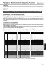
Estimated load inertia ratio