


Timers
16-Bit Timer Setup Examples
Panasonic Semiconductor Development Company MN102H75K/F75K/85K/F85K LSI User Manual
104
Panasonic
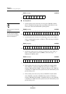
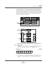
6. Set the TM4NLD bit of the TM4MD register to 1 and the TM4EN bit to 0.
This enables TM4BC and the S-R flip-flop. This step ensures stable opera-
tion. If it is omitted, the binary counter may not count the first cycle. Do not
change any other operating modes during this step.
7. Set TM4NLD and TM4EN to 1. This starts the timer. Counting begins at the
start of the next cycle.
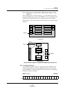
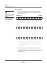
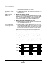
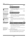
Timer 4 can output a two-phase PWM signal with any phase difference. You must
select up counting. Timer 4 does not operate in STOP mode, when B
OSC
is off. If
you use an external clock, it must be synchronized to B
OSC
.
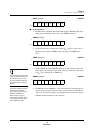
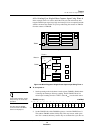
In this procedure, you set the cycle (x’0001’ to x’FFFE’) in the TM4CA register
and the phase difference in the TM4CB register. When the contents of TM4BC
match those of the TM4CB register, T flip-flop B reverses at the beginning of the
next cycle. When the contents of TM4BC match those of the TM4CA register, T
flip-flop A reverses and TM4BC resets at the beginning of the next cycle.
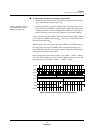
The circuitry is configured so that there are no waveform errors, even when the
output is always high or always low. Counting begins after the TM4EN bit is set
in the TM4MD register.
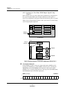
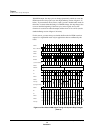
Figure 4-30 below shows the output waveforms for TM4OA and TM40B. Both A
and B interrupts occur when the contents of the binary counter matches those of
the associated compare/capture register. However, B interrupts can only occur if
the TM4CB setting is from 0 to less than TM4CA. This is because when TM4CB
≤ TM4CA, TM4BC never matches TM4CB.
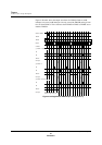
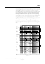
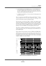
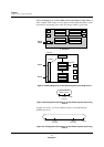
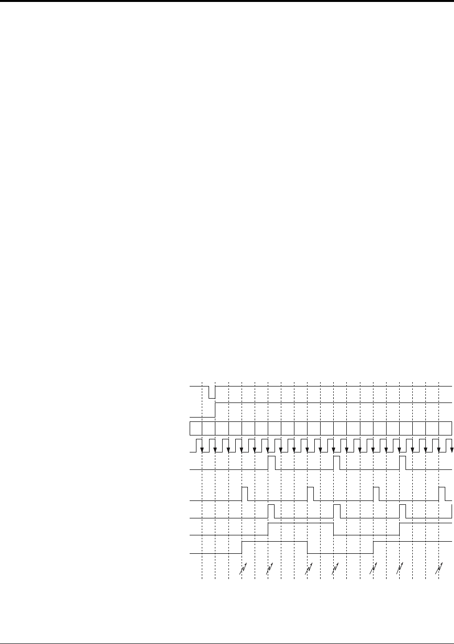
Figure 4-33 Two-Phase PWM Output Timing (Timer 4)
Write to TM4MD
TM4EN
TM4BC
B
OSC
/4
CLRBC4
TMCB = 2
B4
A4
TM4OA
TM4OB
Interrupts
012340 01234012340123
B
A
B
A
B B
A