


Timers
16-Bit Timer Setup Examples
Panasonic Semiconductor Development Company MN102H75K/F75K/85K/F85K LSI User Manual
118
Panasonic
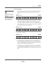
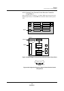
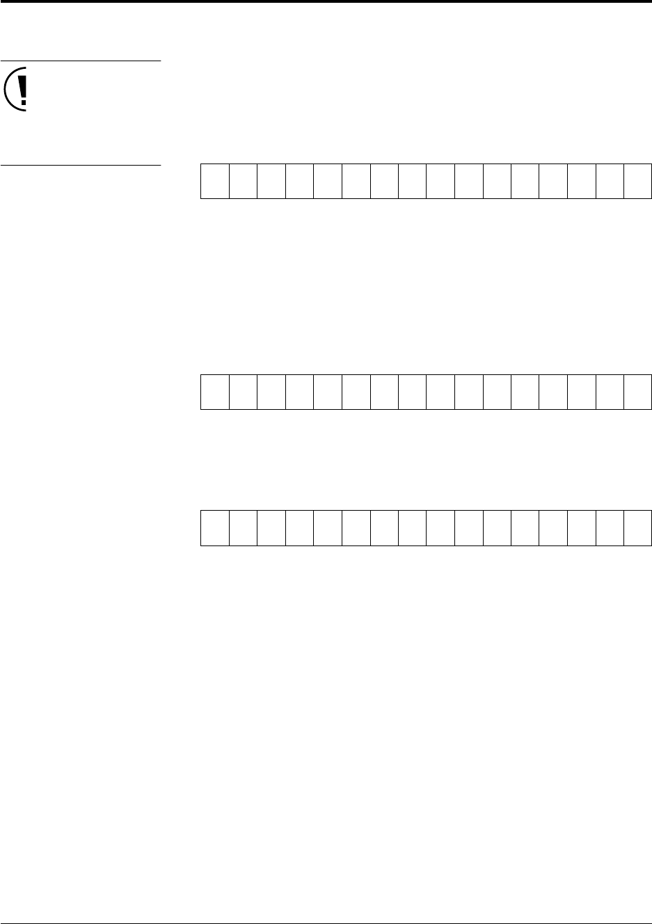
■ To set up timer 5:
Use the MOV instruction for this
setup and only use 16-bit write
operations.
This step stops the TM5BC
count and clears both TM5BC
and the S-R flip-flop to 0.
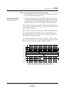
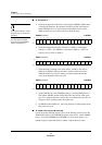
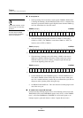
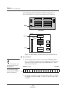
1. Set the operating mode in the timer 5 mode register (TM5MD). Disable timer
5 counting and interrupts. Select up counting. Select B
OSC
/4 as the clock
source.
TM5MD (example) x’00FE90’
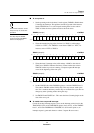
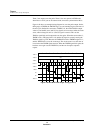
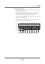
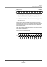
2. Set the timer 5 pulse width in TM5CA (valid settings: x’0001’ to x’FFFF’).
Since the pulse width in this example is two cycles of the B
OSC
/4 clock,
write x’0003’ to TM5CA. TM5BC counts from 0 to 3, and TM5OA outputs
a high signal while the count is 1, 2, and 3. The timer operates essentially the
same as it does during two-phase PWM output.
TM5CA (example) x’00FE94’
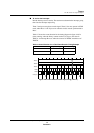
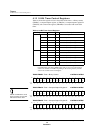
3. Write x’0001’ to TM5CB.
TM5CB (example) x’00FE98’
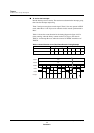
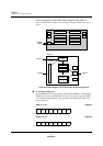
4. Set the TM5NLD bit of the TM5MD register to 1 and the TM5EN bit to 0.
This enables TM5BC and the S-R flip-flop. This step ensures stable opera-
tion. If it is omitted, the binary counter may not count the first cycle. Do not
change any other operating modes during this step.
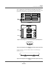
5. On the falling edge of the TM5IB signal, the hardware sets the TM5EN bit
to 1. This means that counting begins at the start of the next cycle after the
TM5IB signal falls. The TM5EN bit serves as the busy flag for the one-shot
pulse.
Bit:1514131211109876543210
TM5
EN
TM5
NLD
——
TM5
UD1
TM5
UD0
TM5
TGE
TM5
ONE
TM5
MD1
TM5
MD0
TM5
ECLR
TM5
LP
TM5
ASEL
TM5
S2
TM5
S1
TM5
S0
Setting:0000001100011 or 0011
Bit:1514131211109876543210
TM5
CA15
TM5
CA14
TM5
CA13
TM5
CA12
TM5
CA11
TM5
CA10
TM5
CA9
TM5
CA8
TM5
CA7
TM5
CA6
TM5
CA5
TM5
CA4
TM5
CA3
TM5
CA2
TM5
CA1
TM5
CA0
Setting:0000000000000011
Bit:1514131211109876543210
TM5
CB15
TM5
CB14
TM5
CB13
TM5
CB12
TM5
CB11
TM5
CB10
TM5
CB9
TM5
CB8
TM5
CB7
TM5
CB6
TM5
CB5
TM5
CB4
TM5
CB3
TM5
CB2
TM5
CB1
TM5
CB0
Setting:0000000000000001