


On-Screen Display
Setting Up the OSD
Panasonic Semiconductor Development Company MN102H75K/F75K/85K/F85K LSI User Manual
190
Panasonic
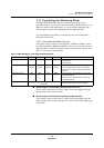
■ To set up the vertical position:
Cursor
♦ Write the vertical position of the cursor to the SVP[9:0] field
(x’007F14’).
♦ Valid range: x’3F0’ − (no. of H scan lines) ≥ SHP ≥ x’03’
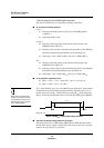
When you write new values to
the GIVP and CIVP fields, the
settings take effect on the next
VSYNC pulse. This means that
changes are reflected in the next
display screen rather than the
current one.
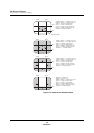
Graphics
♦ Write the vertical position of the first line in the display to the
GIVP[9:0] field (x’007F18’).
♦ Write the position of the second and all following lines in the GVP[9:0]
field of the graphics display RAM data for the preceding line.
♦ Valid range: x’3F0’ − (no. of H scan lines) ≥ GIVP/GVP ≥ x’03’
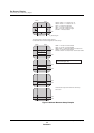
Text
♦ Write the vertical position of the first line in the display to the
CIVP[9:0] field (x’007F1C’).
♦ Write the position of the second and all following lines in the CVP[9:0]
field of the text display RAM data for the preceding line.
♦ Valid ranges: x’3F0’ − (no. of H scan lines) ≥ CIVP/CVP ≥ x’03’
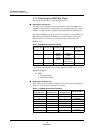
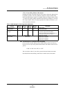
VP range calculation example
The base graphics line height is 16 dots, or H scan lines. If the graphics line you
are positioning displays at 2x the base height, the number of H scan lines is:
16 × 2 = 32 = x’20’ H scan lines
The valid range of settings for GVP is:
x’3F0’ − x’20’ = x’3D0’ ≥ GVP ≥ x’03’
■
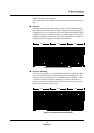
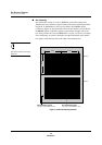
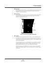
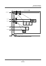
About the vertical start position on the screen
The vertical position, or VP settings (SVP, GVP, and CVP) determine where the
upper edge of cursor, graphics, and text lines start on the screen. You can set this
value for all of the layers in H scan line units. Using the same VP settings for all
the layers makes them all start at the same vertical position.