


IR Remote Signal Receiver
Block Diagram
MN102H75K/F75K/85K/F85K LSI User Manual Panasonic Semiconductor Development Company
217
Panasonic
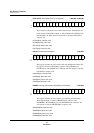
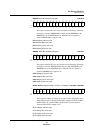
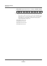
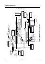
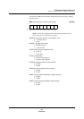
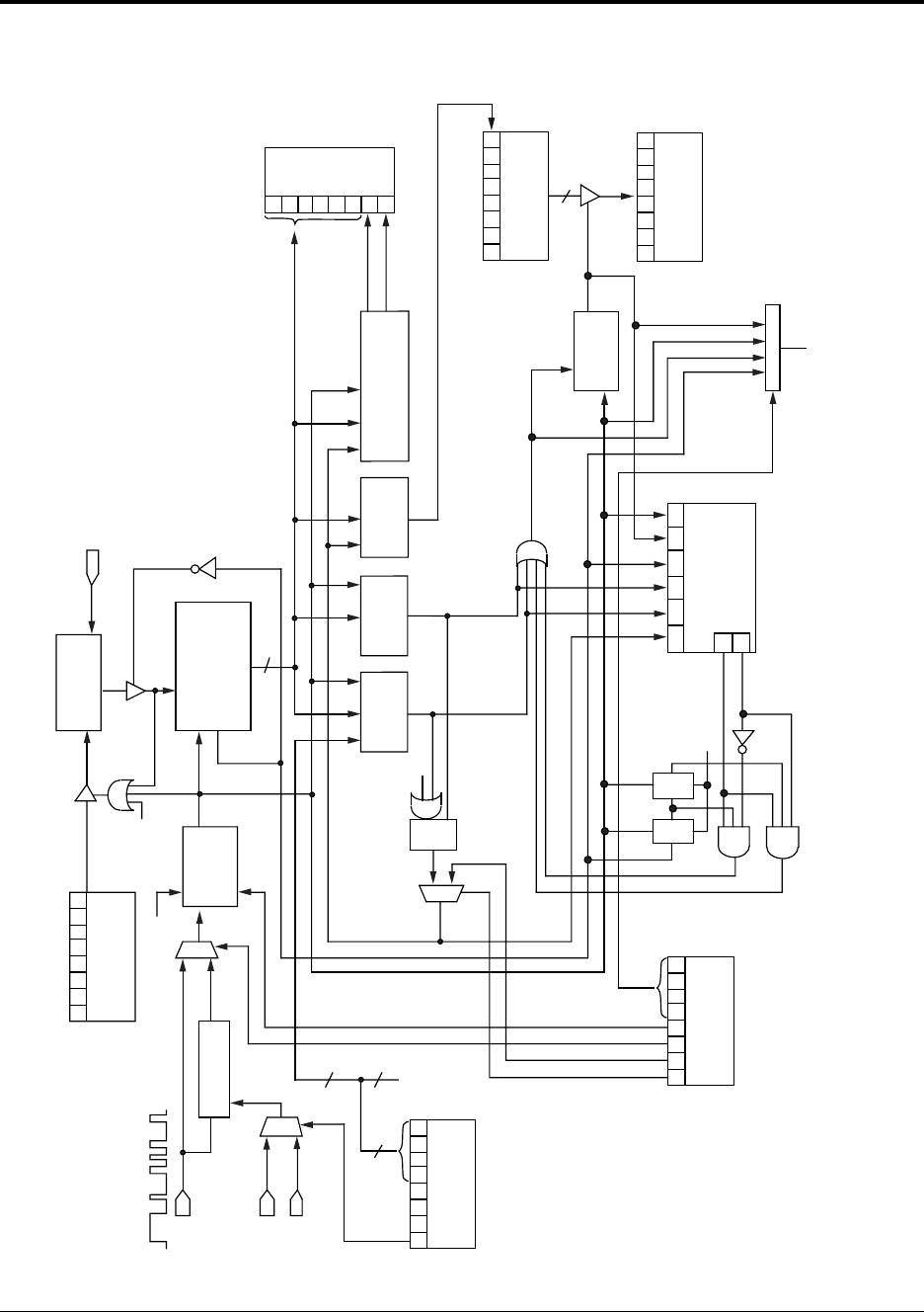
8.2 Block Diagram
Figure 8-1 IR Remote Signal Receiver Block Diagram
54321
0
MUX
CK CK
7654
3210
MUX
CK
MUX
R
CK
4
RMTC: x’007E04’
Frequency
division
counter
PWM3
(375 kHz, 2.7 s)
Clock supply stops upon overflow
Ts-
R
CK
6-bit counter
(Overflow) counter value
12 MHz, 0.083 s
Sampling
CK
Polarity select
Noise filter
CK
Remote input signal
RMIN
Sampling
PWM6
(21.3 s)
PWM8
(85.5 s)
6
6
2
x’00’
(2 LSBs)
RMLD: x’007EAC’
RMIR: x’007EA2’
Q
R
S
Reset
CK
CK
Short/long
detection
Short
Long
6-bit counter overflow
Remote signal edge detection
Reset
RMIS: x’007EA0’
Q
R
D
CK
Q
R
D
CK
RMTR: x’007EAA’
RMSR: x’007EA8’
8
8-bit
data
receive
counter
RMCS: x’007EA6’
Loading of 8-bit
received data
Counter value
7
6
7654
3210
7654
3210
7654
3210
7654
3210
7654
3210
Data format
detection
5-/6-bit
leader
detection
Edge
detection
circuit
Write
instruction
Interrupt masking
RMCICL: x’00FC76’
RMCIR (bit 4)
HEAMA
leader
detection