


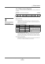

H Counter
H Counter Operation
Panasonic Semiconductor Development Company MN102H75K/F75K/85K/F85K LSI User Manual
308
Panasonic
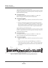
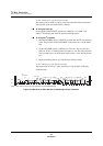
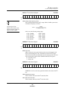
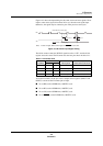
Figure 14-3 shows the input timing for the count source and reset signals. Never
input a count source signal in less than 245 ns (t
1
) after the reset signal input.
Otherwise, the signal may be counted as part of the previous count cycle.
The 10-bit counter counts the HSYNC signal from 0 to x’3FF’, and the 10-bit
register stores the count. The H counter uses the four pins shown in table 14-1.
To use the H counter, set the port 4 and 5 output control registers (P4OUT and
P5OUT) to 0 and set the H counter pins to input.
■ To use HI0, set the P4DIR3 bit (x’00FFE4’) to 0.
■ To use HI1, set the P4DIR4 bit (x’00FFE4’) to 0.
■ To use VI0, set the P5DIR2 bit (x’00FFE5’) to 0.
■ To use VSYNC
, set the P5DIR4 bit (x’00FFE5’) to 0.
Note: In this example, HI0 is active high and VSYNC is active low.
Figure 14-3 H Counter Input Signal Timing
Table 14-1 H Counter Pins
Pin Name
Pin No.
Description Alternative Functions
H75K H85K
HI0 17 45 Count source pin P43/TM5IOB
HI1 16 46 Count source pin P44/TM5IC
VI0 6 53 Count reset pin P52/IRQ4
VSYNC
2 55 Count reset pin P54/IRQ5
HI0
HI0 counted on the rising edge
VI0
VSYNC counted on the falling edge
t
1
t
2
t
1
≥ 245 ns t
2
≥ 200 ns