


Interrupts
Interrupt Setup Examples
Panasonic Semiconductor Development Company MN102H75K/F75K/85K/F85K LSI User Manual
40
Panasonic
2.2 Interrupt Setup Examples
2.2.1 Setting Up an External Pin Interrupt
In this example, an interrupt occurs on a falling-edge signal from the IRQ0 (P00)
external interrupt pin, and the interrupt priority level is 5.
On reset, the external edge setting in the EXTMD register is low (b’00’ = active-
low interrupt), and the IQ0IR bit of the IQ0ICL register is 0.
■
Enabling external interrupt 0
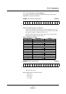
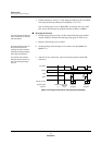
1. Set the interrupt conditions for the IRQ0 (P00) pin. For this example, set the
IQ0TG[1:0] bits of EXTMD to b’10’ (negative-edge-triggered interrupt).
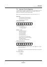
EXTMD (example) x’00FCF8’
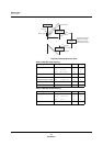
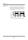
2. Cancel any existing interrupt requests and enable IRQ0 interrupts. To do
this, set the IQ0IR bit of IQ0ICL to 0, set the IQ0LV[2:0] bits of IQ0ICH to
b’101’ (priority level 5), and set the IQ0IE bit to 1.
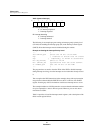
IQ0ICL (example) x’00FC48’
IQ0ICH (example) x’00FC49’
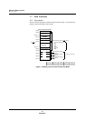
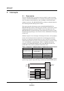
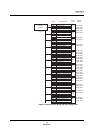
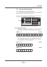
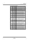
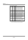
Figure 2-4 Block Diagram of External Pin Interrupt
IRQ0
P5
P0
P2
P1
P3
CORE
Interrupts
Timers 0-5
ROM, RAM
Bus Controller
Serial I/Fs
ADC
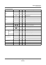
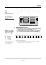
Bit: 15 14 13 12
11 10 9 8
76543210
0000
IQ5TG
1
IQ5TG
0
IQ4TG
1
IQ4TG
0
IQ3TG
1
IQ3TG
0
IQ2TG
1
IQ2TG
0
IQ1TG
1
IQ1TG
0
IQ0TG
1
IQ0TG
0
Setting:———— 0 0 0000000010
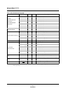
Bit:76543210
— — — IQ0IR — — — IQ0ID
Setting:00000000
Bit:76543210
— IQ0LV2 IQ0LV1 IQ0LV0 — — — IQ0IE
Setting:01010001