


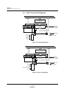
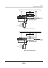

Low-Power Modes
Turning Individual Functions On and Off
MN102H75K/F75K/85K/F85K LSI User Manual Panasonic Semiconductor Development Company
75
Panasonic
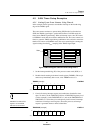
3.2 Turning Individual Functions On and Off
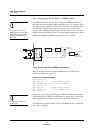
You cannot set the PLL function
control bit during NORMAL mode.
You must set it from the SLOW
mode.
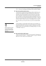
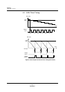
To turn off the OSD block to save
power:
1. Write a 0 to OSD (OSD1, bit10).
2. Wait for the next VSYNC input.
3. Write a 0 to OSDPOFF(PCNT0,
bit 7), turning the clock off.
If you turn the clock off before the
VSYNC input, power usage may
not drop or the microcontroller
may halt.
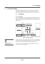
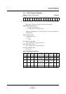
The MN102H75K/85K allows you to turn each peripheral function on or off
through writing to the registers. You can significantly reduce power consumption
by turning off unused functions. Table 3-1 shows the register bits controlling on
and off for each function block. The ADC used for the OSD and CCD functions
is turned off on reset. Write a 1 to the function to enable it, when necessary.
You cannot read from or write to the registers associated with a function that is
disabled. Turning on the function enables register reads and writes.
See the sections on each of these peripheral functions for more information.
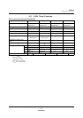
Table 3-1 Peripheral Function On/Off Switches
Block Name Description Bit Name Address Operation Reset Value
OSD
OSD block control OSDPOFF
PCNT0, x’00FF90’, bit
7
0:OSD block off
1:OSD block enabled
0
OSD function control OSD
OSD1, x’007F06’, bit
10
0:OSD function off
1:OSD function on
0
OSD register R/W control
OSDREG
E
PCNT2, x’00FF92’, bit
0
0:OSD register R/W off
1:OSD register R/W enabled
0
CCD
ADC control for CCD1 ADC1ON
PCNT0, x’00FF90’, bit
5
0:ADC for CCD1 off
1:ADC for CCD1 enabled
0
ADC control for CCD0 ADC0ON
PCNT0, x’00FF90’, bit
4
0:ADC for CCD0 off
1:ADC for CCD0 enabled
0
CCD1 function control VBI1OFF
PCNT0, x’00FF90’, bit
1
0:CCD1 block off
1:CCD1 block enabled
0
CCD0 function control VBI0OFF
PCNT0, x’00FF90’, bit
0
0:CCD0 block off
1:CCD0 block enabled
0
PLL PLL function control PLLPOFF
PCNT0, x’00FF90’, bit
6
0:PLL block enabled
1:PLL block off
0
H counter H counter function control HCNTOFF
PCNT0, x’00FF90’, bit
3
0:H counter block enabled
1: H counter block off
0
IR remote
signal receiver
IR remote signal
receiver function control
RMCOFF
PCNT0, x’00FF90’, bit
2
0:IR remote signal receiver
block off
1:IR remote signal receiver
block enabled
0
I
2
CI
2
C function control I2COFF
PCNT2, x’00FF92’, bit
2
0:I
2
C block enabled
1:I
2
C block off
0
PWM PWM function control PWMOFF
PCNT2, x’00FF92’, bit
1
0:PLL block enabled
1:PLL block off
0