


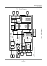
On-Screen Display
OSD Operation
Panasonic Semiconductor Development Company MN102H75K/F75K/85K/F85K LSI User Manual
158
Panasonic
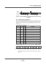
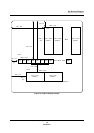
7.5.7 Conditions for VRAM Writes
■ Text layer
Set CHP, CVP, GHP, and GVP
for every line in the VRAM. If
you do not, a software
processing error may occur.
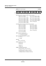
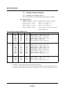
1. The lead data for each line must be the color control code (COL) or the char-
acter code (CC). Never place the horizontal position (CHP), vertical position
(CVP), or repeat (CCB) codes at the beginning of a line. (If the lead data is
CC, with no COL specification, the character will be text palette color 1, and
the background will be color 2.)
2. Place each line’s horizontal and vertical position data (CHP and CVP), in
that order, at the end of the preceding line.
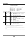
3. Insert the color control code (COL) before the character code (CC). You do
not need to meet condition 3 in the closed-caption mode, since COL can
carry over in that mode.
4. A character code (CC) must immediately precede a repeat character/blank
code (CCB), and a color control code (COL) or character code (CC) must
follow it.
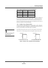
5. To indicate the last line of a display, make the CHP and CVP values for the
last line smaller than those in the currently displayed line. In addition, write
a 1 to the last line flag of the text layer (CLAST).
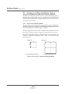
6. Two text lines (but no more) can overlap on the screen. The lower line takes
priority, appearing to lie on top of the higher line.
7. If the horizontal sync signal is asserted while the microcontroller is access-
ing CHP and CVP, that line and the next line may not display properly. (For
details, see section 7.10.4, “Setting Up the OSD Display Position,” on page
189.)
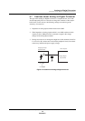
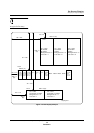
■
Graphics layer
1. Place each line’s horizontal and vertical position data (GHP and GVP), in
that order, at the end of the preceding line. Do not place GHP and GVP at the
start of a line.
2. To indicate the last line of a display, make the GHP and GVP values for the
last line smaller than those in the currently displayed line. In addition, write
a 1 to the last line flag of the graphics layer (GLAST).
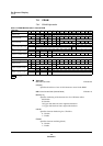
3. Two graphic lines (but no more) can overlap on the screen. The lower line
takes priority, appearing to lie on top of the higher line.
4. If the horizontal sync signal is asserted while the microcontroller is access-
ing GHP and GVP, that line and the next line may not display properly. (For
details, see section 7.10.4, “Setting Up the OSD Display Position,” on page
189.)