


Closed-Caption Decoder
Functional Description
Panasonic Semiconductor Development Company MN102H75K/F75K/85K/F85K LSI User Manual
234
Panasonic
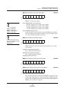
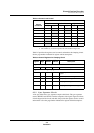
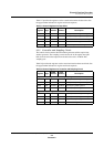
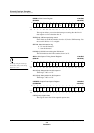
Table 9-7 provides the registers used to control and monitor the data slicer. See
the page number indicated for register and bit descriptions.
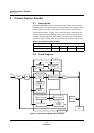
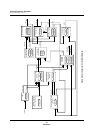
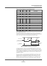
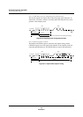
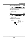
9.3.5 Controller and Sampling Circuit
The control circuit contains the CRI window generator and the caption data
window generator. The sampling circuit extracts the 16-bit caption data (503
kHz) from the serial data output from the data slicer at the 12-MHz ADC
sampling rate.
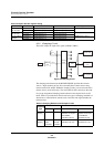
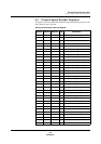
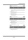
Table 9-8 provides the registers used to control and monitor these two blocks. See
the page number indicated for register and bit descriptions.
Table 9-7 Control Registers for Data Slicer
Register Page
CCDO
Address
CCD1
Address Description
CRI1S 240 x’007E10’ x’007E30’ CRI capture start timing control register 1
CRI1E 241 x’007E12’ x’007E32’ CRI capture stop timing control register 1
MAXMIN 238 x’007E02’ x’007E22’ CRI interval maximum and minimum register
SLICE 238 x’007E04’ x’007E24’ VBI data slice level register
FCCNT 237 x’007E00’ x’007E20’ VBI decoding format select register
Table 9-8 Control Registers for Controller and Sampling Circuit
Register Page
CCDO
Address
CCD1
Address Description
Registers for detecting CRI and generating sampling clock
CRI2S 241 x’007E14’ x’007E34’ CRI capture start timing control register 2
CRI2E 241 x’007E16’ x’007E36’ CRI capture stop timing control register 2
CRIFA 240 x’007E0C’ x’007E2C’ CRI frequency width register A
CRIFB 240 x’007E0E’ x’007E2E’ CRI frequency width register B
Registers for controlling data capture
DATAS 241 x’007E18’ x’007E38’ Data capture start timing control register
DATAE 242 x’007E1A’ x’007E3A’ Data capture stop timing control register
CAPDATA 239 x’007E0A’ x’007E2A’ Caption data capture register
HNUM 239 x’007E06’ x’007E26’ HSYNC count register