


Closed-Caption Decoder
Closed-Caption Decoder Registers
MN102H75K/F75K/85K/F85K LSI User Manual Panasonic Semiconductor Development Company
245
Panasonic
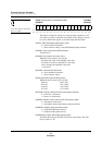
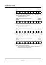
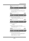
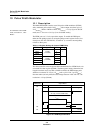
BSP[5:0]: Sync separator level for pedestal clamping
Sync separator level = (sync tip level/2) + BSP[5:0]. The valid range is
x’00’ to x’3F’.
PSP[5:0]: Sync separator level for sync tip clamping
Valid range: x’00’ to x’3F’
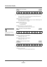
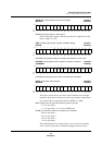
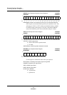
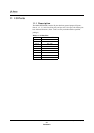
CLAMP: Clamping Control Register x’007ECC’
(CLAMPW x’007EEC’)
Use this register to set the clamping mode (sync tip or pedestal clamping).
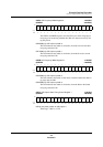
PCLV[6:0]: Pedestal clamping level setting
Set the reference level for pedestal clamping in this field. The valid range
is x’00’ to x’7F’.
VBION: VBI setting
0: VBI off
1: VBI on
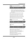
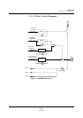
SAFE: Clamping current source select
This bit is the capacity switch for (5) and (6) in figure 9-5 on page 229.
0: High current source ((5) and (6) capacity high)
1: Medium current source ((5) and (6) capacity low)
CLMODE[1:0]: Clamping mode setting
00: Automatic switching (depends on the cycle state)
01: Sync tip clamping only
10: Pedestal clamping only
11: Clamping off
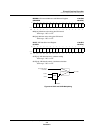
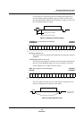
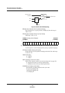
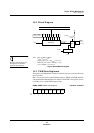
Figure 9-15 BSP and PSP Multiplexing
Bit:1514131211109876543210
— PCLV6 PCLV5 PCLV4 PCLV3 PCLV2 PCLV1 PCLV0 SAFE — —
VBI
ON
——
CL
MODE
1
CL
MODE
0
Reset:0100000000000000
R/W: R R/W R/W R/W R/W R/W R/W R/W R/W R R R/W R R R/W R/W
MUX
Compare
CLMODE
BSP
PSP
Composite signal
from ADC
Composite sync