


Timers
8-Bit Timer Setup Examples
Panasonic Semiconductor Development Company MN102H75K/F75K/85K/F85K LSI User Manual
82
Panasonic
4.5 8-Bit Timer Setup Examples
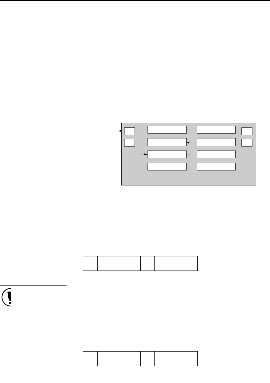
4.5.1 Setting Up an Event Counter Using Timer 0
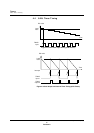
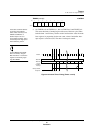
In this example, timer 0 generates an underflow interrupt on the fourth rising
edge of the TM0IO signal.
The event counter continues to operate during STOP mode. In all modes but
STOP, the TMnIO signal input is synchronized to B
OSC
. In STOP mode, the
timer counts TMnIO signal directly. When an interrupt occurs, the CPU returns
to NORMAL mode after the oscillator stabilization wait. The event counter con-
tinues to count the TMnIO signal during stabilization wait, and at the same time
that the CPU returns to NORMAL mode, the event counter begins counting the
signal resulting from the B
OSC
sampling of the TMnIO signal input.
1. Set the interrupt enable flag (IE) of the processor status word (PSW) to 1.
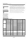
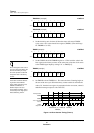
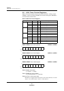
2. Disable timer 0 counting in the timer 0 mode register (TM0MD). This step is
unnecessary immediately after a reset, since TM0MD resets to 0.
TM0MD (example) x’00FE20’
TM2UDICH, TM0UDICL, and
TM0UDICH are 8-bit access
registers. Use the MOVB
instruction to access them.
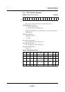
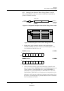
3. Cancel all existing interrupt requests and enable timer 0 underflow inter-
rupts. To do this, set the TM2UDLV[2:0] bits of TM2UDICH (priority level
4 in this example), set the TM0UDIE bit to 1, and set the TM0UDIR bit of
TM0UDICL to 0. (Note that you set the priority level for timer 0 interrupts
in the timer 2 interrupt control register.) From this point on, an interrupt
request is generated whenever timer 0 underflows.
TM2UDICH (example) x’00FC71’
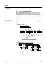
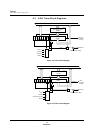
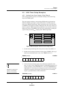
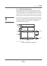
Figure 4-9 Block Diagram of Event Counter Using Timer 0
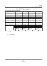
Bit:76543210
TM0
EN
TM0
LD
————
TM0
S1
TM0
S0
Setting:00000000
TM0I
P2
P6
P4
P5
CORE
Interrupts
Timers 0-3
Timers 4-5
ROM, RAM
Bus Controller
Serial I/Fs
ADC
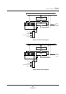
Bit:76543210
—
TM2UD
LV 2
TM2UD
LV 1
TM2UD
LV 0
———
TM2UD
IE
Setting:01000000