


IR Remote Signal Receiver
Description
Panasonic Semiconductor Development Company MN102H75K/F75K/85K/F85K LSI User Manual
216
Panasonic
8 IR Remote Signal Receiver
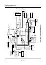
8.1 Description
The MN102H75K/85K contains a remote signal receiver that processes signals in
two formats: Household Electrical Appliance Manufacturers Association
(HEAMA) format and 5-/6-bit format. This chapter provides an overview of each
block in the circuit and describes the operation of the receiver.
fSYSCLK = 12 MHz in all of the
examples and descriptions in
this section. In addition,
fPWM1 = fSYSCLK/23,
fPWM3 = fSYSCLK/25,
fPWM5 = fSYSCLK/27,
fPWM6 = fSYSCLK/28, and
fPWM8 = fSYSCLK/210.
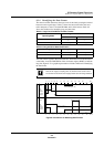
The remote signal is input through the RMIN pin. Each time the edge detection
circuit detects the active edge of the signal, the 6-bit counter resets and the
sampling clock, T
S
, starts counting. T
S
is formed by dividing PWM3 by the value
in the frequency division control register, RMTC. The clock status register,
RMCS, which can be read at any time, holds the current value of the 6-bit
counter.
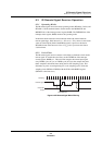
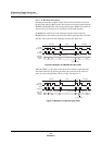
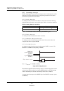
The remote signal contains a leader, data, and a trailer, in that order. The micro-
controller shifts received data into the LSB of the reception data shift register,
RMSR. After it receives 8 bits, it loads the contents of RMSR to the reception
data transfer register, RMTR.