


Timers
16-Bit Timer Setup Examples
Panasonic Semiconductor Development Company MN102H75K/F75K/85K/F85K LSI User Manual
110
Panasonic
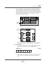
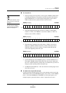
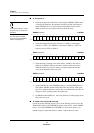
■ To service the interrupts and calculate the signal width:
1. Run the interrupt service routine. The routine must determine the interrupt
group, then clear the interrupt request flag.
Ignore the flags when calculat-
ing the signal width, even when
TM3CA is the larger value.
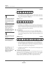
2. Calculate the number of cycles the TM4IA signal stays high. Save the con-
tents of TM4CA and TM4CB to the data registers, then subtract the contents
of TM4CA from the contents of TM4CB. Since TM4LP is set to 0, the dif-
ference will be the correct value even if TM4CA is greater than TM4CB.
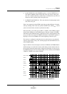
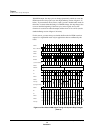
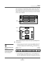
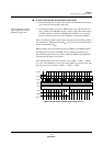
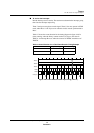
Timer 4 can input a two-phase capture signal. You must select up counting. Timer 4
does not operate in STOP mode, when B
OSC
is off. If you use an external clock, it
must be synchronized to B
OSC
.
TM4CA captures the count on the rising edge of TM4IA, and TM4CB captures
the count on the rising edge of TM4IB. A timer 4 capture B interrupt occurs
when TM4CB captures the count, and the contents of TM4CA and TM4CB are
read during the interrupt service routine.
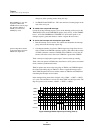
In the example timing chart shown in figure 4-38, x’000A’ – x’0007’ = x’0003’,
or 3 cycles. The calculation is correct even when TM4CA is the larger value. The
flags are ignored, so for instance, x’0003’ – x’FFFE’ = x’0005’.
Figure 4-38 Two-Phase Capture Input Timing (Timer 4)
001234567
07
0A
8 9 A B C D E F 10 11 12
TM4EN
TM4BC
BOSC/4
TM4CA
TM4CB
TM4IA
TM4IB
Interrupt
B
A-7=3