


MN102H75K/F75K/85K/F85K LSI User’s Manual
Modified Points From MN102H75K/F75K To MN102H75K/F75K/85K/F85K
MN102H75K/F75K/85K/F85K LSI User Manual Panasonic Semiconductor Development Company
1
Panasonic
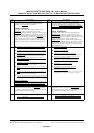
page Before Modify page After Modify
P16
This manual is intended for assembly-language programming
engineers. It describes the internal configuration and hardware
functions of the MN102H75K
microcontrollers.
Using This Manual
The chapters in this manual deal with the internal blocks of the
MN102H75K
. Chapters 1 to 5 provide an overview of the
MN102H75K
’s general specifications, interrupts, power modes, timers,
and serial connections. Chapters 6 to 10 describe the on-screen display
and other specialized functions available with the MN102H75K
.
Chapter 11 provides the I/O port specifications, chapter 12 describes the
ROM correction feature, chapter 13 describes the I
2
C interface, and
chapter 14 describes the H scan line counter. Appendix A provides a
register map, and Appendix B describes the flash EEPROM version.
P16
This manual is intended for assembly-language programming
engineers. It describes the internal configuration and hardware
functions of the MN102H75K and MN102H85K microcontrollers.
Except when discusssiing differing specifications,this manual refers to
the two microcontrollers as a single device : MN102H75K/85K.
Using This Manual
The chapters in this manual deal with the internal blocks of the
MN102H75K/85K
. Chapters 1 to 5 provide an overview of the
MN102H75K/85K
’s general specifications, interrupts, power modes,
timers, and serial connections. Chapters 6 to 10 describe the on-screen
display and other specialized functions available with the
MN102H75K/85K
. Chapter 11 provides the I/O port specifications,
chapter 12 describes the ROM correction feature, chapter 13 describes
the I
2
C interface, and chapter 14 describes the H scan line counter.
Appendix A provides a register map, and Appendix B describes the
flash EEPROM version.
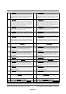
P17
■ MN10200 Series Linear Addressing High-Speed Version LSI User Manual
(Describes the core hardware.)
■ MN10200 Series Linear Addressing High-Speed Version Instruction Manual
(Describes the instruction set.)
■ MN10200 Series Linear Addressing High-Speed Version C Compiler User
Manual: Usage Guide
(Describes the installation, commands, and options for the C compiler.)
■ MN10200 Series Linear Addressing High-Speed Version C Compiler User
Manual: Language Description
(Describes the syntax for the C compiler.)
■ MN10200 Series Linear Addressing High-Speed Version C Compiler User
Manual: Library Reference
(Describes the standard libraries for the C compiler.)
■ MN10200 Series Linear Addressing High-Speed Version Cross-Assembler User
Manual
(Describes the assembler syntax and notation.)
■ MN10200 Series Linear Addressing Version C Source Code Debugger User
Manual
(Describes the use of the C source code debugger.)
■ MN10200 Series Linear Addressing Version PanaX Series Installation Manual
(Describes the installation of the C compiler, cross-assembler, and C source
code debugger and the procedures for using the in-circuit emulator.)
Questions and Comments
We welcome your questions, comments, and suggestions. Please contact the semicon-
ductor design center closest to you. See the last page of this manual for a list of
addresses and telephone numbers. You can also find contact and product information
on the World Wide Web at: http://www.psdc.com/
P17
■ MN102H Series LSI User Manual
(Describes the core hardware.)
■ MN102H Series Instruction Manual
(Describes the instruction set.)
■ MN102H Series C Compiler User Manual: Usage Guide
(Describes the installation, commands, and options for the C compiler.)
■ MN102H Series C Compiler User Manual: Language Description
(Describes the syntax for the C compiler.)
■ MN102H Series C Compiler User Manual: Library Reference
(Describes the standard libraries for the C compiler.)
■ MN102H Series Cross-Assembler User Manual
(Describes the assembler syntax and notation.)
■ MN102H Series C Source Code Debugger User Manual
(Describes the use of the C source code debugger.)
■ MN102H Series Installation Manual
(Describes the installation of the C compiler, cross-assembler, and C source
code debugger and the procedures for using the in-circuit emulator.)
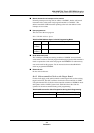
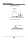
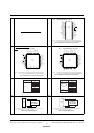
P24
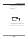
Figure 1-5 shows the address space for the MN102H75K.The internal
ROM contains the instructions and the font data for the on-screen dis-
play (OSD), in any location. The internal RAM contains the MCU data
and the VRAM for the OSD, in any location.
P24
Figure 1-5 shows the address space for the MN102H75K/85K.The
internal ROM contains the instructions and the font data for the on-
screen display (OSD), in any location. The internal RAM contains the
MCU data and the VRAM for the OSD, in any location
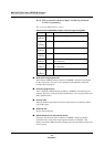
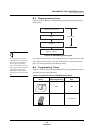
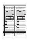
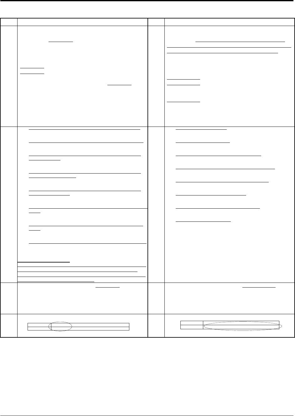
P27 P27
I/O ports
66
Package
84-pin QFP
I/O ports
66(MN102H75K/F75K) / 50(MN102H85K/F85K)
Package
84-pin QFP(MN102H75K/F75K) / 64-pin SDIL(MN102H85K/F85K)