


MN102HF75K Flash EEPROM Version
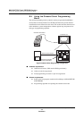
Using the Onboard Serial Programming Mode
Panasonic Semiconductor Development Company MN102H75K/F75K/85K/F85K LSI User Manual
322
Panasonic
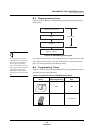
B.4.3 Microcontroller Hardware Used in Onboard Serial Pro-
gramming
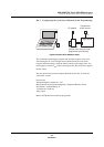
B.4.3.1 Serial Writer Interface Description
The microcontroller contains the following interface hardware for serial pro-
gramming of the flash ROM:
■ One 8-bit serial interface (use serial interface 1):
♦ Data transmission and reception synchronize with external clock
♦ Transmission bit LSB first
♦ Maximum clock speed ≥ 10 MHz
♦ Positive I/O logic
■ Two I/O pins:
♦ SBT1 and SBD1 pins (with alternate I/O port functions)
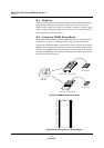
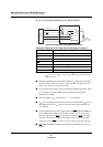
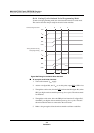
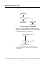
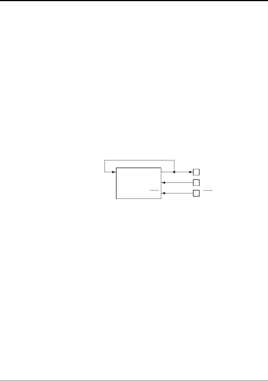
B.4.3.2 Serial Writer Interface Block Diagram
When programming the memory, you need not be aware of these microcontroller
hardware connections. However, it is vital that you take these connections into
account when designing your target board, so that the serial writer can program
the device correctly, and so that SBD1 and SBT1 are dedicated pins for the serial
writer, preventing other user circuits from communicating with the device.
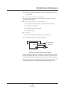
Figure B-7 Serial Writer Interface Block Diagram
8-bit serial interface
(use serial interface 1)
TXD
RXC,TXC
P25, TM4IOB, SBD1
P24, TM4IC, SBT1
RXD
RST
RST