


I
2
C Bus Controller
I
2
C Interface Setup Examples
MN102H75K/F75K/85K/F85K LSI User Manual Panasonic Semiconductor Development Company
301
Panasonic
13.6.1.3Setting Up the Second Interrupt
When the microcontroller receives the data x’85’ from the slave device, it returns
an ACK = 0 signal and the I
2
C bus controller generates an interrupt. At this point,
implement the following settings:
■
To set up the interrupt:
Set the I2C0ICH and I2C0ICL register pair (x’00FC9C’) to x’0100’. This
enables I
2
C interrupts and clears the previous interrupt request.
■
To set up the I
2
C registers:
1. Read the I2CDREC register (x’007E42’) to determine the I
2
C bus controller
status.
2. Since the communication will end when the microcontroller receives the
next data byte, set the I2CDTRM register (x’007E40’) to x’0100’. This sets
STA to 0, STP to 0, ACK to 1, and the transmission data to x’00’. With this
setting, the microcontroller returns an ACK = 1 signal on the ninth clock.
13.6.1.4Setting Up the Third Interrupt
When the microcontroller receives the data x’33’ from the slave device, it returns
an ACK = 1 signal and the I
2
C bus controller generates an interrupt. At this point,
implement the following settings:
■
To set up the interrupt:
Set the I2C0ICH and I2C0ICL register pair (x’00FC9C’) to x’0100’. This
enables I
2
C interrupts and clears the previous interrupt request.
■
To set up the I
2
C registers:
1. Read the I2CDREC register (x’007E42’) to determine the I
2
C bus controller
status.
2. Since the transfer has ended, set the I2CDTRM register (x’007E40’) to
x’0300’. This sets STA to 0, STP to 1, ACK to 1, and the transmission data
to x’00’. With this setting, the microcontroller issues a stop condition and
frees the bus.
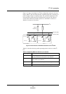
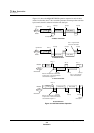
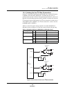
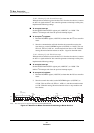
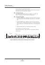
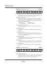
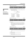
Note: The circled areas are signals output from the MN102H75K/85K.
Figure 13-7 Waveform for Master Transmitter Transitioning to Master Receiver
1
S
R/W
0
ACK
P
Data
(slave address)
11
1
1
1
1
0
ACK
1
1
11
1
0
0
0
0
0
0
00
0
0
ACK
1
1
1
SDA
SCL