


MN102HF75K Flash EEPROM Version
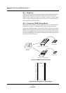
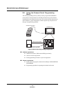
Using the Onboard Serial Programming Mode
MN102H75K/F75K/85K/F85K LSI User Manual Panasonic Semiconductor Development Company
321
Panasonic
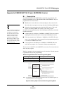
B.4.2 Circuit Requirements for the Target Board
■ During programming, the serial writer supplies V
PP
to the microcontroller.
Install a switch on the target board to toggle between V
PP
supplied by the
serial writer and V
PP
for normal operation.
■ In serial programing a large-scale of current flows through Vpp. See to it that
5V is supplied to Vpp by checking the connection and reducing the
impedance of switches.
■ You must supp ly a V
DD
source of 3.0 V – 3.3 V externally.
■ V
DD
(for level detection) informs the serial writer of the actual V
DD
level of
the target board. If the V
DD
level is too low, the serial writer generates an
error message.
■ Connect pullup resistors on the target board to the RST
, SBT, and SBD pins.
Use a pullup resistor value of 10 kΩ ±10%. Install a switch on the target
board to toggle between RST
for serial programming and RST for normal
operation. Alternatively, install a wired-OR connection. For a wired-OR
connection, disable RST
for normal operation during serial programming.
■ RST
, SBT, and SBD are output from the serial writer through an open con-
nection.
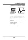
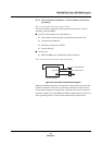
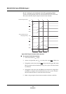
Figure B-6 Target Board–Serial Writer Connection
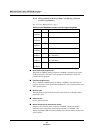
Table B-3 Pin Descriptions for Target Board–Serial Writer Connection
Pin Name Description
V
PP
5-V power supply
V
DD
3.0–3.3 external power supply
V
DD
(for level detection) V
DD
level detection pin for target board
RST
Reset
SBT Serial interface clock supply
SBD Serial interface data supply
GND Ground
Note: 1. During normal microcontroller operation, V
PP
should always be equal to
V
DD
(3.3 ±0.3 V). Apply 5 V to the V
PP
supply only when programming
the flash memory.
Serial
writer
V
PP
= +5 V
GND
SBT
SBD
RST
V
DD
(for level detection)
MCU
SBT1
SBD1
RST
V
PP
External
power sourc
e
3.0 V - 3.3 V
V
DD
GND
10 k
Ω
Target board