


Timers
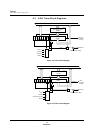
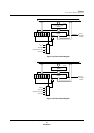
8-Bit Timer Setup Examples
Panasonic Semiconductor Development Company MN102H75K/F75K/85K/F85K LSI User Manual
86
Panasonic
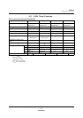
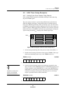
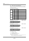
TM2MD (example) x’00FE22’
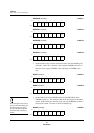
In the bank and linear address-
ing versions of the MN102
series, it was necessary to set
TM0EN and TM0LD to 0
between steps 4 and 5, to
ensure stable operation. This is
unnecessary in the high-speed
linear addressing version.
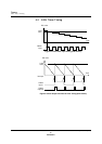
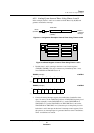
5. Set TM2LD to 0 and TM2EN to 1, then set TM1LD to 0 and TM1EN to 1.
This starts the timers. Counting begins at the start of the next cycle. When
both the timer 1 and 2 binary counters reach 0 and loads the values from the
base registers, in preparation for the next count, a timer 2 underflow inter-
rupt request is sent to the CPU. The timer 1 interrupt is unused.
Access TM2MD and TM1MD
with a 16-bit write, using the
MOV instruction, or set the two
registers consecutively, begin-
ning with TM2MD.
Bit:76543210
TM2
EN
TM2
LD
————
TM2
S1
TM2
S0
Setting:01000010
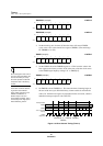
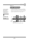
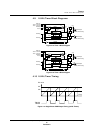
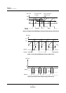
Figure 4-13 Interval Timer Timing (Timers 1 and 2)
00 EA5F
00 EA5F EA5E EA5D 0002 0001 0000 EA5F
B
OSC
/4
TM2,1BR
TM2,1BC
Timer 2
underflow
interrupt
Interrupt enable
Sequence
(1) (2) (3) (4) (5)