


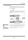
Low-Power Modes
CPU Modes
MN102H75K/F75K/85K/F85K LSI User Manual Panasonic Semiconductor Development Company
73
Panasonic
3.1.2 Exiting from SLOW Mode to NORMAL Mode
The MN102H75K/85K recovers
from power up and reset in
SLOW mode. For normal opera-
tion, the program must switch
the MCU from SLOW to NOR-
MAL mode.
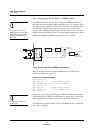
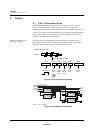
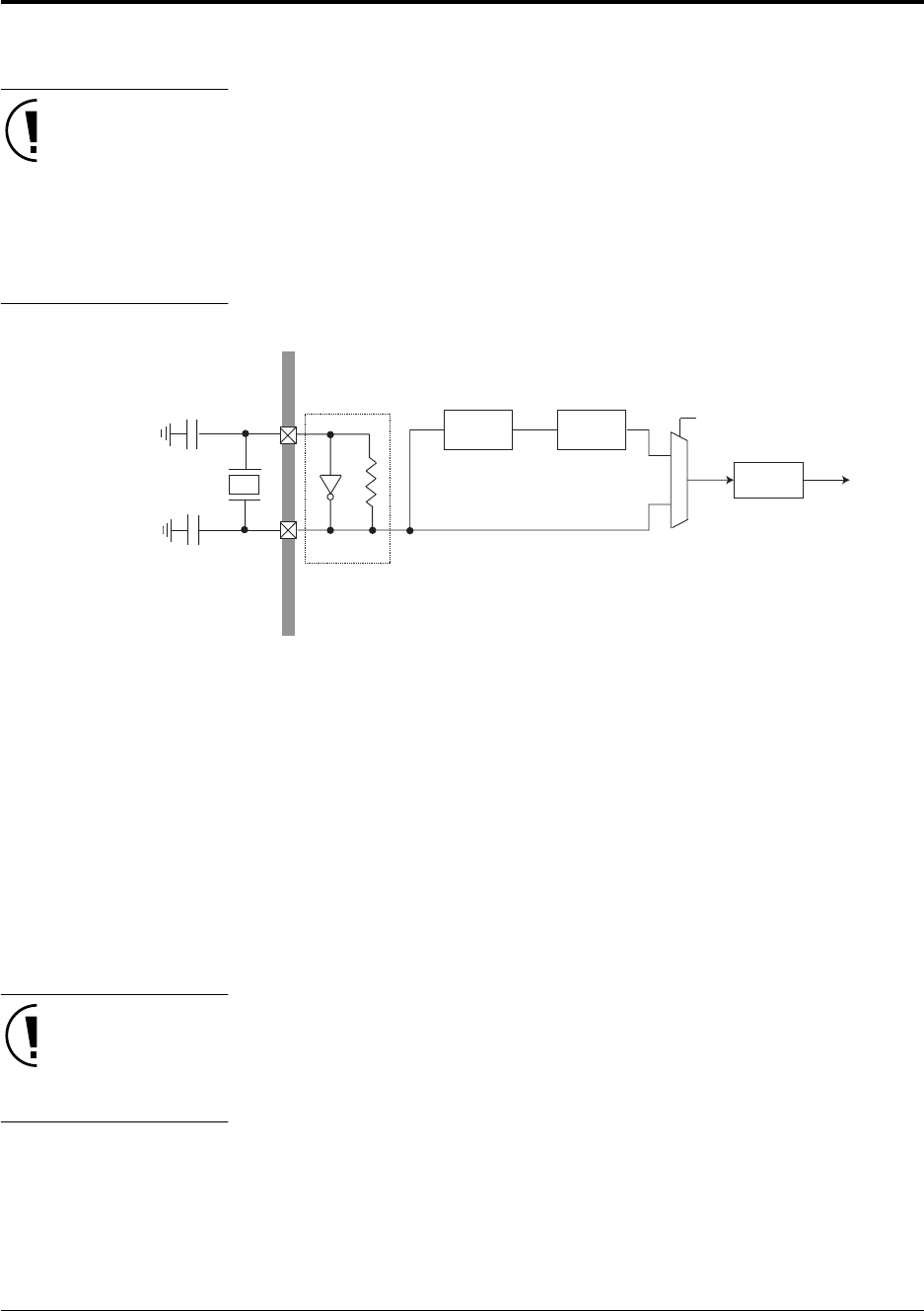
The MN102H75K/85K contains a PLL circuit that, in NORMAL mode, mul-
tiplies the clock input through the OSC1 and OSC2 pins by 12, divides the signal
by 2, then sends the resulting clock to the CPU. (See figure 3-2.) The MCU starts
in SLOW mode on power up and on recovery from a reset. In SLOW mode
(system clock = 2 MHz), the clock from the OSC pins feeds directly to the CPU,
without going through the PLL circuit. This means that the program must switch
the CPU from SLOW to NORMAL mode (system clock = 12 MHz).
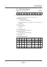
Below is an example routine for exiting SLOW mode. You should run this
routine immediately after power up.
Example 3-1 Exiting SLOW Mode
MOV x’FC00’,A1
MOV (A1),D0 ;Read CPUM register
AND x’FFFD’,D0 ;Invoke IDLE mode
MOV (D0),A1
MOV (A1),D0 ;Read CPUM register
AND x’FFF0’,D0 ;Invoke NORMAL mode
MOV (D0),A1
The OSD cannot display in
SLOW mode.
Because the system clock in SLOW mode is 2 MHz, the OSD does not function.
The specifications also differ for the PWM function and functions such as the IR
remote signal receiver and the H counter that use the PWM waveforms.
For information on invoking SLOW mode from NORMAL mode, see MN102H
Series LSI User Manual.
Figure 3-2 CPU Clock Switch (NORMAL/SLOW Modes)
CPU
12x PLL
circuit
Divide-by-2
circuit
System clock:
SLOW: 2 MHz
NORMAL: 12 MHz
To all function blocks
Clock select
(CPUM register)
Oscillator
Circuit
4 MHz
48 MHz
24 MHz
4 MHz
M
U
X
NORMAL mode
SLOW mode