


H Counter
H Counter Operation
MN102H75K/F75K/85K/F85K LSI User Manual Panasonic Semiconductor Development Company
309
Panasonic
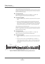
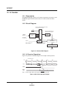
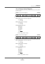
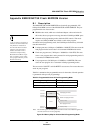
The H counter counts the HSYNC signal for the interval set in the HCCNT0
(x’007EB0’) or HCCNT1 (x’007EB2’) register, latches the count value in the 10-
bit register, then clears the counter. HCCNT0 and HCCNT1 provide six interval
settings:
■ 1024-µs fixed interval obtained by dividing the system clock (12 MHz)
■ 2048-µs fixed interval obtained by dividing the system clock (12 MHz)
■ 4098-µs fixed interval obtained by dividing the system clock (12 MHz)
■ 8096-µs fixed interval obtained by dividing the system clock (12 MHz)
■ Interval from active-edge to active-edge input of VI0 pin
■ Interval from active-edge to active-edge input of VSYNC pin
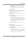
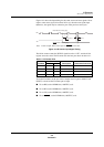
If your application uses one of the fixed clocks based on divided PWM output
(1024, 2048, 4098, or 8096 µs), you must also set up the PWM circuit. (See
section 10, “Pulse Width Modulator,” on page 249.)
To use the H counter, you must
always set the HCNTOFF bit of
the PCNT0 register to 0. To use
the PWM function, always set
the PWMOFF bit of the PCNT2
register (x’00FF92’) to 0.
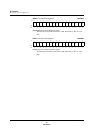
When the count overflows (is greater than x’3FF’), the counter stops counting
and stores the value x’3FF’ in the 10-bit register. At any time, the CPU can
obtain the count value stored in the latch by reading the HCD0 (x’007EB4’) or
HCD1 (x’007EB6’) register.
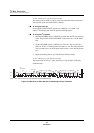
To enable or disable the H counter function, set the HCNTOFF bit of the PCNT0
register (x’00FF90’; see page 286). Disabling this circuit when it is unused can
reduce power consumption.
Because the H counter uses the system clock, it does not operate in STOP mode.