


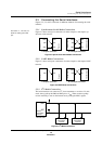
Timers
16-Bit Timer Setup Examples
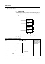
MN102H75K/F75K/85K/F85K LSI User Manual Panasonic Semiconductor Development Company
123
Panasonic
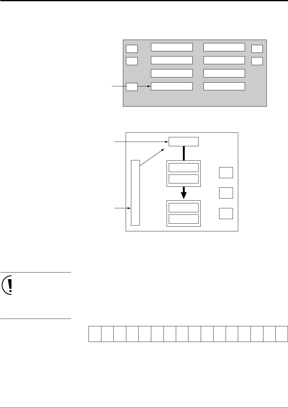
4.11.10Setting Up External Reset Control Using Timer 5
In this example, timer 5 is reset by an external signal while counting up.
■
To set up timer 5:
Use the MOV instruction to set
this data and only use 16-bit
write operations.
This step stops the TM5BC
count and clears both TM5BC
and the S-R flip-flop to 0.
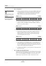
1. Set the operating mode in the timer 5 mode register (TM5MD). Disable
timer 5 counting and interrupts. Select up counting. Since the TM5IC signal
will reset the counter asynchronously, set the TM5ECLR bit to 1. Select
B
OSC
/4 as the clock source.
TM5MD (example) x’00FE90’
2. Set the value to which timer 5 will loop (valid settings: x’0001’ to x’FFFF’).
For TM5BC to count from x’0000’ to x’1FFF’, for instance, write x’1FFF’
to TM5CA.
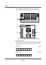
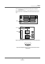
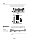
A. Chip Level
B. Block Level
Figure 4-52 Block Diagram of External Reset Control Using Timer 5
TM5IC
P3
P5
CORE
Interrupts
Timers 0-3
Timers 4-5
ROM, RAM
Bus Controller
Serial I/Fs
ADC
P2
P6
P4
reset
TM5BC
Timer 5
TM5CA
TM5CB
TM5IC
B
OSC
/4
TQ
TQ
R
S
Q
Controller
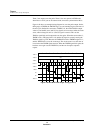
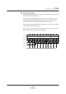
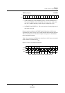
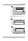
Bit:1514131211109876543210
TM5
EN
TM5
NLD
——
TM5
UD1
TM5
UD0
TM5
TGE
TM5
ONE
TM5
MD1
TM5
MD0
TM5
ECLR
TM5
LP
TM5
ASEL
TM5
S2
TM5
S1
TM5
S0
Setting:0000000000110011